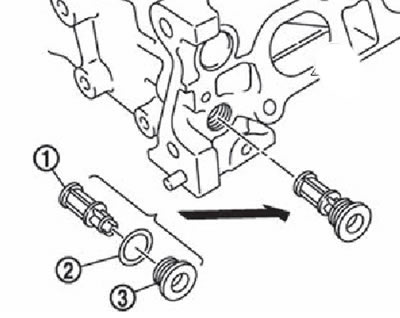
1. Oil filter.
2. Washer.
3. Plug.
2. Install the intake valve opening control solenoid valve directly into the cylinder head and tighten the mounting bolts.
3. Install the valve lifters in the same position that they occupied before removal.
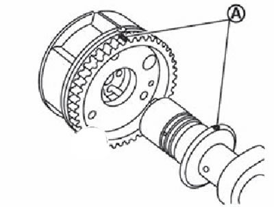
4. Align the inlet camshaft and sprocket timing marks in one line as follows:
Note. This procedure is necessary to prevent the alignment pin from aligning with the mismatched hole after installing the intake camshaft and its sprocket.
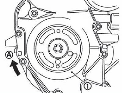
Place appropriate labels (A) along one line passing through the locating pin of the front surface of the intake camshaft (1) and stars (2), as it shown on the picture.
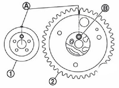
Place the alignment mark against the hole (IN) intake camshaft sprockets (2), as it shown on the picture.
5. Place the intake camshaft sprocket between the cylinder head and front cover.
Note. Locating pin hole (A) should be directed upwards.
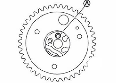
Attention. Make sure in advance that the locating pin is in the end of the camshaft.
6. Install camshafts.
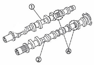
1. Exhaust camshaft.
2. Intake camshaft.
A. Identification marks.
Note.
- The intake and exhaust camshafts differ from each other in the different shape of the rear.
- The camshafts are installed in the cylinder head so that the dowel pins (A) on the front of the camshafts were in the position shown in the figure.
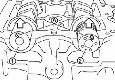
1. Exhaust camshaft.
2. Intake camshaft.
Note. The arrow points to the top side.
Note. For the correct operation of the gas distribution mechanism, it is necessary to place the camshafts strictly in the position shown in the figure.
7. Install the intake camshaft sprocket onto the intake camshaft as follows:
Align setting mark (A) according to step 4. Carefully align the dowel pin with the hole, then install the sprocket.
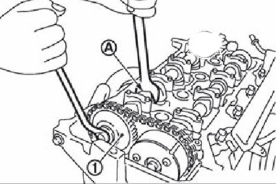
Raise the front of the intake camshaft (1) and screw on the bolt.
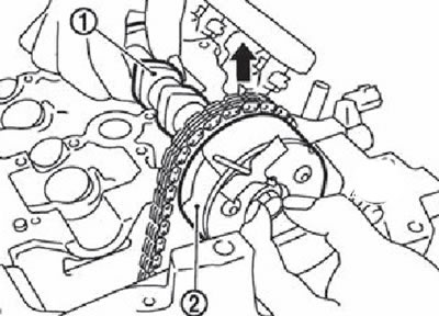
1. Intake camshaft.
2. Intake camshaft sprocket.
8. Place a piece of thin cloth (IN) under the bottom of the camshaft, then install a ring wrench on the front of the raised intake camshaft (1).
9. Tighten the mounting bolt.
Attention. Hold the camshaft from turning at the hexagonal part (A).
10. Return the intake camshaft to the cylinder head.
11. Install the timing chain (1), aligning the installation mark (applied when removing the drive chain) (IN) with setting mark (lateral knurling) (A) on the intake camshaft sprocket (2).
12. Install the camshaft covers (№№2-5), placing the identification marks on the top surface as shown in the figure.
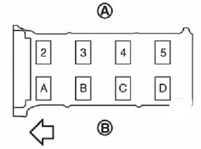
A. Release side.
B. Inlet side.
Note. The deal in the picture shows the front of the engine. Install the camshaft covers so that the identification marks are correctly read from the intake side of the engine.
13. Tighten the camshaft cover bolts in several steps in the sequence shown in the figure.
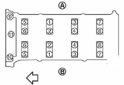
A. Release side.
B. Inlet side.
Note. The arrow in the figure shows the front of the engine.
Tighten bolts nos. 9-11 to 2 Nm.
Tighten bolts nos. 1-8 in sequence to 2 Nm.
Tighten all bolts in sequence to 5.9 Nm.
Tighten all bolts in sequence to 10.4 Nm.
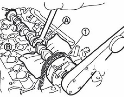
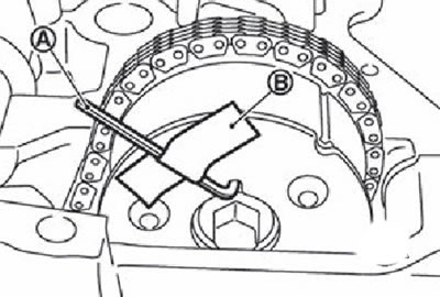
14. Set the sprocket (2) on the exhaust camshaft, aligning the marks (A), applied when removing the drive chain, with alignment mark (stamp) (IN) exhaust camshaft sprockets.
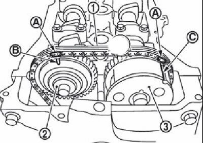
1. Timing chain drive.
2. An asterisk of a final camshaft.
3. Intake camshaft sprocket.
A. Paint marks on drive chain links.
B. Installation mark (stamp).
C. Installation mark (lateral knurling).
Note. If the position of the dowel pin does not match the hole, it is easy to move the exhaust camshaft for adjustment.
15. Tighten the bolt for fastening the sprocket of the exhaust pumping shaft (1).
Attention.
- To fix the camshaft, hold it with a wrench on the hexagonal part (A).
- Check that the marks made when removing the drive chain and all timing marks on the camshaft sprockets are in the correct position.
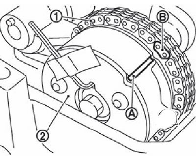
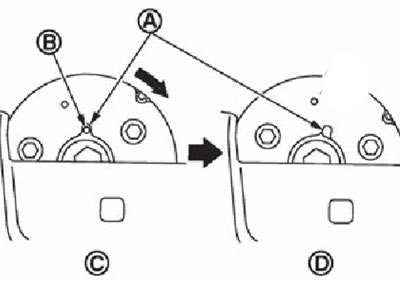
16. Remove lock pin (A) and tension the drive chain by slightly turning the crankshaft pulley clockwise.
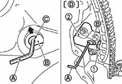
1. Plunger.
2. Chain tensioner.
A. Locking pin.
B. Lever.
C. Lever hole.
D. Front cover removed
17. Install screw plug (2) into the front cover (1) engine. Apply sealant to the threads of the plug and tighten it.
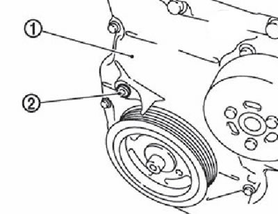
Note. Use original sealant or equivalent.
18. Return the intake camshaft sprocket to its most extreme position as follows:
Remove lock pin (A) from the intake camshaft.
A. Locking pin.
V. Insulating tape (scotch).
Slightly rotate the pulley (1) crankshaft clockwise (A) and lift the intake camshaft sprocket to its most extreme position. At the beginning of the rotation of the capped shaft, the intake camshaft sprocket will turn, however, with further rotation of the camshaft blades, they will also begin to rotate, thus reaching the most extreme position.
If you start to rotate the crankshaft, the intake camshaft sprocket will also begin to rotate. Turning, it will also make the blades rotate (camshaft), as a result of which they will be set to the position of the maximum retardation angle.
A. Lock pin groove.
B. Lock pin hole.
C. Maximum lead angle.
D. Maximum retardation angle (locking pin in engagement).
The maximum lag angle can be checked visually - the groove for the locking pin (A) must be rotated clockwise.
By slightly turning the crankshaft counterclockwise, you can verify that the locking pin is engaged by observing how the blades (camshaft) and the zipper move at the same time.
19. Install the camshaft position sensor (phase sensor) on the back of the cylinder head and tighten the mounting bolts.
20. Check and adjust valve clearances.
21. Install the remaining parts in the reverse order of removal.