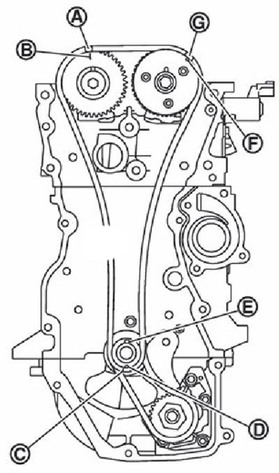
Note. The figure shows the alignment of the timing marks on the drive chain and the corresponding sprockets after the components have been installed.
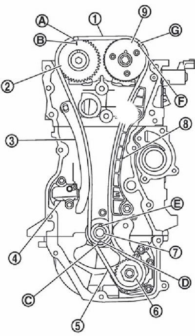
1. Timing chain drive.
2. An asterisk of a final camshaft.
3. Drive chain tensioner shoe.
4. Drive chain tensioner.
5. Oil pump drive chain.
6. Oil pump sprocket.
7. Crankshaft sprocket.
8. Drive chain damper.
9. Intake camshaft sprocket.
A. Dark blue link.
B. Installation mark (stamp).
C. Orange link.
D. Reference mark (stamp).
E. Crankshaft key (pointing up).
F. Reference mark (lateral knurling).
G. Dark blue link.
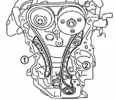
1. Install the crankshaft sprocket and oil pump drive parts:
Simultaneously install the crankshaft sprocket (1), oil pump drive chain (2) and oil pump sprocket (3).
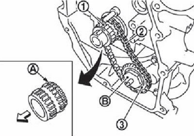
Note. The arrow points to the front of the engine.
Install the crankshaft sprocket so that the side with the pseudo gear (A) was directed towards the rear of the engine.
Install the oil pump sprocket so that the hexagon side (IN) was directed towards the rock part of the engine.
Note. There are no alignment marks on the oil pump drive components.
Holding the top of the oil pump shaft with a Torx bit (size: E8), tighten the oil pump sprocket nuts.
1. Crankshaft sprocket.
2. Oil pump drive chain.
3. Oil pump sprocket.
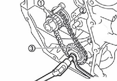
Install chain tensioner (1and why insert the housing onto the axle (IN), while inserting the spring into the fixing hole (A) front surface of the cylinder block. Check that the oil pump drive chain is tensioned after installation.
2. Install the timing chain:
Install the chain by lining up all the matching skeins on the links and sprockets.
A. Dark blue link.
B. Installation meta (stamp).
C. Orange link.
D. Reference mark (stamp).
E. Crankshaft key (pointing up).
F. Installation Meta (lateral knurling).
G. Dark blue link.
If the alignment coils do not match, turn the camshaft a little to correct the position.
Recheck the position of the alignment marks on each sprocket and timing chain after installing the chain, holding it with your hands.
To avoid slipping of the sprocket teeth in the drive chain, do not rotate the crankshaft and camshaft until the engine front cover is installed.
3. Install tensioner shoe (1) and sedative (2) drive chain.
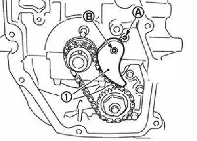
4. Install the drive chain tensioner (1):
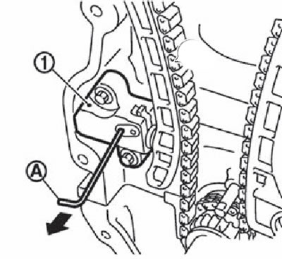
Lock the plunger in the fully compressed position using the locking pin (A), and then install the tensioner mechanism.
Carefully remove the lock pin after the tensioner mechanism is installed.
5. Again check the position of the adjusting rolls of all sprockets and the drive chain.
6. Install the crankshaft front oil seal into the front cover,
7. Install the engine front cover:
Apply a continuous bead of sealant to the engine front cover mounting surfaces as shown.
Note. Use genuine Nissan sealant or equivalent.
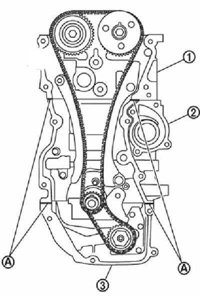
1. Cylinder head.
2. Block of cylinders.
3. Upper part of the oil pan.
A. Sealant Application Areas (∅ 3.0-4.0 mm).
Apply a continuous bead of sealant to the engine front cover.
Note. Use genuine Nissan sealant or equivalent.
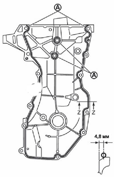
A. Sealant application area (03.0-4.0 mm).
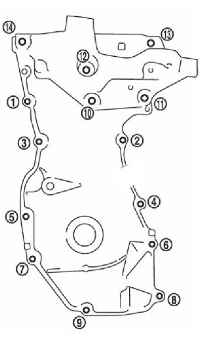
Tighten the bolts in the sequence shown.
After tightening the bolts, it is necessary to check their tightening value again in the specified sequence.
Attention. Excess sealant must be removed from surfaces.
8. Insert the crankshaft pulley, aligning it with the crankshaft key.
Note. When using a plastic hammer to install the crankshaft pulley, tap on the center of the pulley (not around the edges).
Attention. When installing, take care not to damage the lips of the front oil seal.
9. Tighten the crankshaft pulley bolt:
Note. To tighten the crankshaft pulley bolt, fix the pulley with a special holder.
Apply fresh engine oil to the threads and seating surfaces of the crankshaft pulley bolt.
Tighten the crankshaft pulley bolt to 35.0 Nm.
Mark with paint (IN) on the crankshaft pulley opposite any corner mark (A), corresponding to the six edges of the bolt (1).
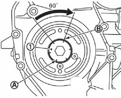
Tighten the bolt another 60°clockwise (tightening angle), focusing on the corner marks.
10. Make sure that the crankshaft rotates freely clockwise from the effort of the hands.
11. Install the remaining parts in the reverse order of removal.