Shift lever and rods
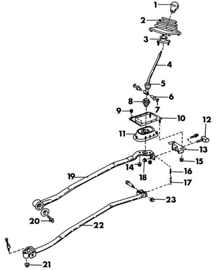
Parts of the shift mechanism on the outside of the gearbox
1 - shift lever handle; 2 - dust cover; 3 - shift lever guide; 4 - switching lever; 5 - upper support of the gear lever; 6 - bushings; 7 - round seal; 8 - dustproof nozzle; 9 - nut, 0.5-0.6 Nm; 10 - rubber gasket; 11 - frame support of the shift lever; 12 - damper, only on an injection engine; 13 - holder; 14 - nut, 12-15 Nm; 15 - nut. 12-15 Nm; 16 - gum return spring; 17 - return spring; 18 - nut, 22-30 Nm; 19 - stabilizer bar; 20 - bolt, 37-50 Nm; 21 - nut, 14-18 Nm; 22 - switching rod; 23 - nut, 18-24 Nm
1. Loosen the dust cover around the shift lever and remove it from the lever upwards.
2. Place a thick rag around the shift lever head and unscrew the head using water pump pliers. Make sure that the pads of the pliers do not damage the lever head.
3. Raise the car and unscrew the shift bar and the support bar on the side of the gearbox from the underside (see illustration).
4. Remove the four bolts and nuts of the shift lever support (illustration below) and remove the entire support with the rods located on it.
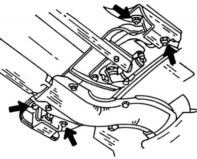
Fastening of the shift lever support on the underside of the vehicle.
5. Installation is carried out in the reverse order. You must comply with all of the illustrations tightening moments. The shift lever support is secured with nuts on the underside of the bottom.
Replacement parts of the shift mechanism
On illustrations shows the wiring diagram of the switching unit. If you need to replace any parts, you can use the illustration. Lubricate all parts with a small amount of grease when assembling. All O-rings must be replaced even if they still look satisfactory.