Removing
Turn locking ring counterclockwise. Remove the automatic transmission or CVT wire connector upwards.
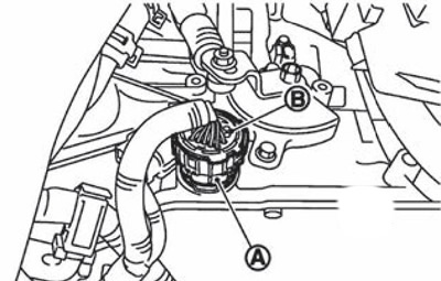
Automatic transmission:
A. Locking ring.
B. AT wire connector.
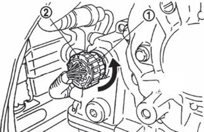
Variable speed drive:
1. Locking ring.
2. Automatic transmission wire connector.
Installation
1. Align mark (A) on the connector housing with the label (IN) on the locking ring. Insert the automatic transmission or CVT wire connector, then turn the snap ring clockwise.
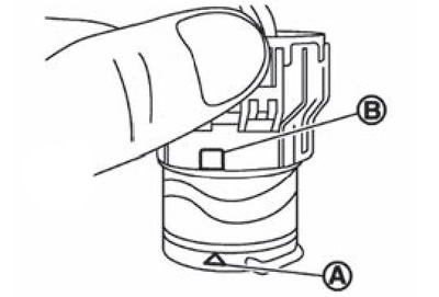
2. Turn the locking ring clockwise until the mark (A) on the connector body is not aligned with the protrusion (IN) on the locking ring as shown in the pictures (correct connection state).
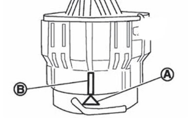
Attention.
The mark needs to be aligned carefully (A) on the connector housing about the protrusion (IN) on the locking ring. Avoid incomplete locking of the connector (shown in the picture).
Do not confuse ledge (IN) with elastic protruding parts of the connector.
