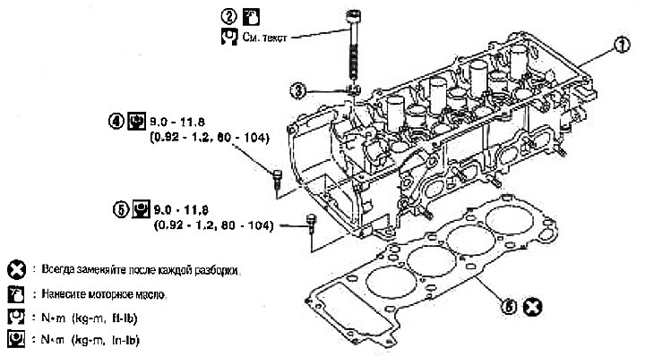
1. Cylinder head assy; 2. Cylinder head bolt; 3. Washer; 4. Auxiliary cylinder head bolt; 5. Auxiliary cylinder head bolt; 6. Gasket
Removing
1. Relieve fuel pressure. See chapter Engine management system.
2. Drain the engine coolant. See chapter Lubrication system and engine cooling system.
3. Remove the following components:
- protective pad from the front right fender;
- alternator and air conditioning compressor drive belt; see section «Drive belts»;
- air duct and air cleaner assembly; see section «Air cleaner and air duct»;
- the top of the intake manifold; see section «upper intake manifold»;
- fuel injectors and fuel tube assembly; see section «Fuel injectors and fuel pipe»;
- upper and lower radiator hoses; see chapter Lubrication system and engine cooling system;
- generator and generator bracket; see chapter electrical equipment;
- exhaust manifold and three-way catalytic converter; see section «Exhaust manifold and three-way catalytic converter»;
- ignition coils; see section «Ignition coil»;
- valve cover; see section «Valve lid»;
- camshaft; see section «camshaft»;
- heated oxygen sensor harness bracket; see section «Exhaust manifold and three-way catalytic converter»;
- outlet pipe, thermostat, engine coolant temperature sensor and heater tube; see chapter Lubrication system and engine cooling system;
- suction tube fixing bolt; see chapter Lubrication system and engine cooling system.
Attention: Fix the engine under the bottom of the oil pan.
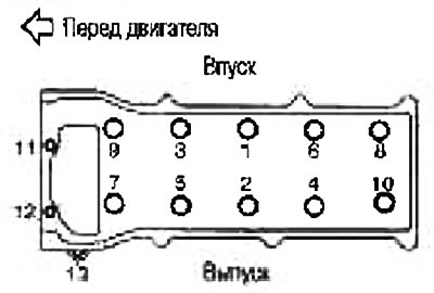
4. Remove the cylinder heads assembly by loosening the bolts in the reverse order to that shown in the figure.
5. Remove the gasket from the cylinder head
Check after removal
Outside diameter of cylinder head bolts
The cylinder head bolts are tightened using the plastic zone method. If the difference between «d1» And «d2» exceeds the limit value, replace the bolts with new ones.
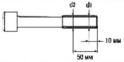
Limit (d1-d2): 0.12 mm.
If a narrowing of the outer diameter is found at a location other than «d2», label it as a dot «d2».
Installation
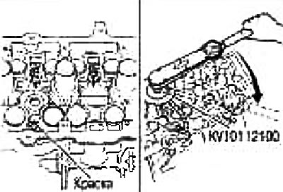
1. Apply sealant evenly to the places indicated in the figure and install a new gasket on the head.
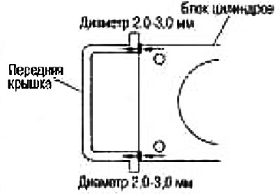
Use branded sealant or equivalent.
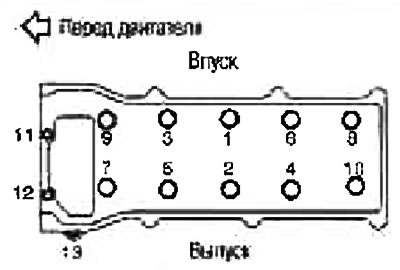
2. Install the cylinder head assembly and tighten the No. 1-10 bolts in the order indicated by numbers in the figure.
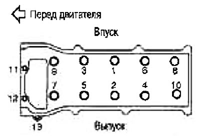
Attention: In paragraph «With» loosen the bolts in the reverse order to that shown in the figure.
Note: Bolts #11-13 should be tightened in step 3 after bolts #1-10 have been tightened.
- A. Apply fresh engine oil to the threads and seating surfaces of the bolts.
- b. Tighten the bolts with a torque of 61.7-71.7 Nm (6.3-7.3 kg m).
- With. Fully loosen to 0 N.m (0 kg m).
- d. Tighten the bolts with a torque of 22.5-32.5 N.m (2.3-3.3 kg m).
- e. Tighten the bolts 90-95°clockwise (norm: 90°) (corner tightening).
Attention: Check the tightening angle with a protractor wrench (special tool). Avoid judging by eye without the use of tools.
Check the angle of tightening on the scale of the protractor key.
3. Tighten the auxiliary bolts (№№11-13) in the order indicated by the numbers in the figure.
4. After this operation, installation is carried out in the reverse order of removal.