Removing
1. Raise the vehicle and remove the wheels from the vehicle.
2. Remove the lock plate from the rack. Disconnect the brake hose from the rack. See chapter Brake system.
3. Remove the ABS wheel sensor from the steering knuckle. See chapter Brake system.
Caution: Do not pull on the wheel sensor wiring harness.
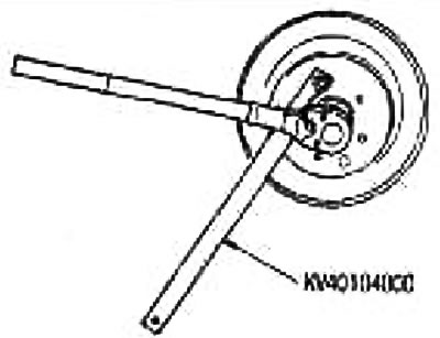
4. Loosen the locknuts with a wrench (special tool).
5. Remove steering draft from a rotary fist. If it is difficult to remove, use a ball joint puller (suitable special tool).
Caution: To prevent damage to the threads and the ball joint puller to come off (suitable special tool) tighten the locknut by hand.
6. Turn off a bolt fixing a rotary fist and a rack.
Caution: Do not bend the driveshaft pivot more than 22°. Securely fix the steering knuckle so as not to overstretch the sliding joint.
7. Remove the drive shaft from the steering knuckle using a puller (suitable special tool).
Attention:
- When removing the drive shaft, do not bend the joint more than 22°. Also, do not overstretch the sliding hinge.
- Do not lift the drive shaft with the axle shaft fixed by grasping only the intermediate shaft.
- Do not allow the drive shaft inserted into the gearbox to hang down without the countershaft support, wheel pivots and other components.
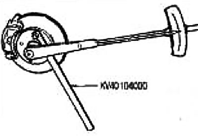
8. Disconnect the drive shaft from the transmission using a wheel wrench or similar tool as shown.
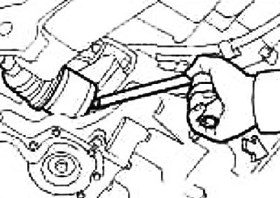
Caution: When removing the drive shaft from the vehicle, be careful not to touch the brake hose, ABS wheel sensor wiring, or other components with it. Do not damage the dust shield.
Make sure the ring clip is attached to the end.
Check after removal
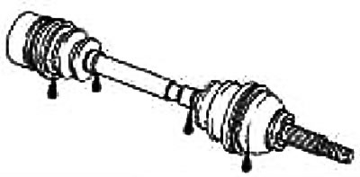
Move the hinge up/down, left/right and axially. Make sure the movement is smooth and there is no significant play. Listen for the sound of air or grease leaking.
Check for cracks and damage on the boots and for leaks of grease.
Check for damage to the clips of the covers.
Installation
1. In order not to damage the differential oil seal, before installing the drive shaft, first put the protection on the oil seal (special tool).
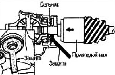
2. Align the drive shaft splines with the gearbox splines.
3. While holding the intermediate shaft and wheel-side joint, apply pressure and insert the sliding joint rod into the differential.
Caution: Make sure the ring clip is fully engaged.
Oil seal protection: Special tool No. KV39107900
4. On vehicles with a support bearing, secure the drive shaft with the support bearing holder.
Caution: Before tightening the support bearing retainer bolts, make sure that the drive shaft support bearing is fully seated in the bracket. Also make sure that a rubber o-ring is inserted between the support bearing and the bracket.
5. Tighten the support bearing holder bolts in the order indicated by the numbers in the figure.
Tightening torque: 21 Nm (2.1 kg m)
6. Tighten the support bearing holder bolts in the order indicated by the numbers in the figure.
Tightening torque: 21 Nm (2.1 kg m)
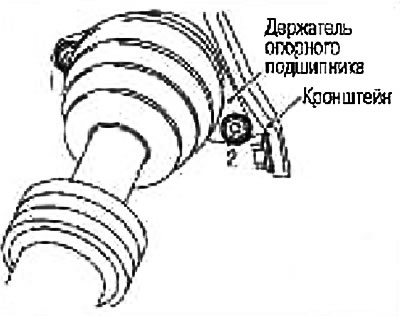
Note: Second pass tightening should be done with a torque wrench.
7. Insert the drive shaft into the steering knuckle and tighten the lock nut.
8. Tighten the bolts securing the steering knuckle to the rack. For tightening torques, see section "Front suspension».
9. Fix a brake hose on a rack a lock plate.
10. Press the tie rod into the steering knuckle. For tightening torques, see section «Front suspension».
11. Install the ABS wheel sensor. See chapter Brake system.
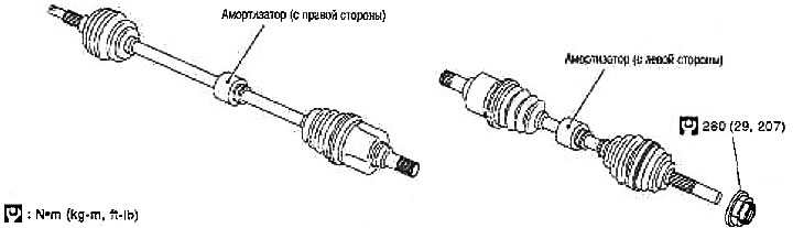
12. Tighten the locknut to the required torque using a wrench (special tool).
Tightening torque: 280 Nm (29 kg m)
13. Install the wheels and lower the lift.