Drive shaft cover. Replacement
Caution: If noise or vibration is coming from the drive shaft, replace the drive shaft assembly.
1. Raise the vehicle and remove the wheels from the vehicle.
2. Disconnect the wiring connectors from the ABS wheel sensors. See chapter Brake system.
3. Disconnect a brake hose from a rack. See chapter Brake system.
4. Remove the ABS wheel sensor from the steering knuckle. See chapter Brake system.
Caution: Do not pull on the wheel sensor wiring harness.
5. Remove the brake caliper assembly from the brake disc and hang the cylinder body on the wire. See chapter Brake system.
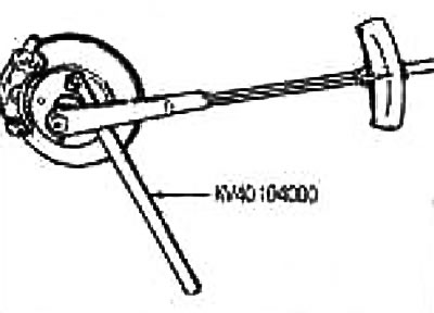
6. Loosen the locknuts with a wrench (special tool).
7. Turn off a bolt fixing a rotary fist and a rack.
Caution: Do not bend the driveshaft pivot more than 22°. Securely fix the steering knuckle so as not to overstretch the sliding joint.
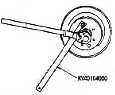
8. Remove the drive shaft from the steering knuckle using a puller (suitable special tool).
Attention:
- When removing the drive shaft, do not bend the joint more than 22°. Also, do not overstretch the sliding hinge.
- Do not lift the drive shaft with the axle shaft fixed by grasping only the intermediate shaft.
- Do not allow the drive shaft inserted into the gearbox to hang down without the countershaft support, wheel pivots and other components.
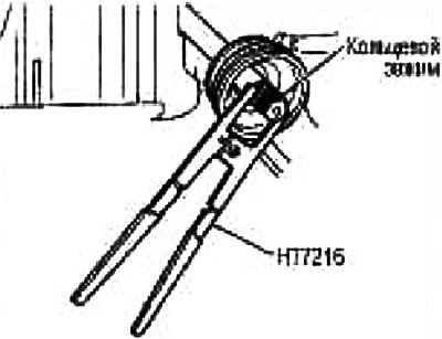
9. Remove boot clips, then remove boot from hinge assembly.
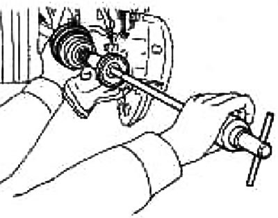
10. Screw on the drive shaft puller (suitable special tool) at least 30 mm on the threads of the pivot assembly.Supporting the drive shaft with one hand, remove the pivot assembly using an impact tool (suitable special tool) from the shaft.
Attention:
- Center the impact puller and drive shaft and remove with firm and even force.
- If the pivot assembly cannot be removed, try again after removing the drive shaft from the vehicle.
11. Remove the boot from the shaft.
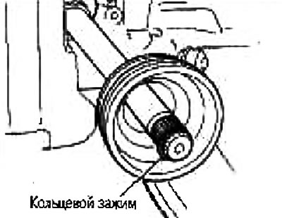
12. Remove the ring clamp from the shaft.
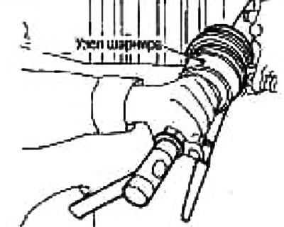
13. Wipe old grease off the pivot assembly with paper towels while rotating the yoke.
Caution: Perform a visual inspection to ensure there are no cuts, cracks, or kinks on the hinge assembly. Also check for debris from the road and metal debris in the lubricant. If abnormal, replace the pivot assembly as a set.
14. Fill with genuine Nissan grease (see spare parts catalog) into the spline of the pivot assembly until grease flows out of the ball joint groove and spline.
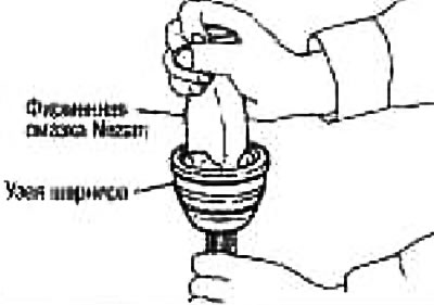
After stuffing with grease, wipe off the old leaked grease with a napkin.
15. In order not to damage the cover during installation, wrap the splined part of the drive shaft with electrical tape. Put a new boot on the shaft and secure with clips.
Note: Place the clamp on the narrow side first.
Attention: Do not reuse clips and case.
16. Remove the tape wrapped around the shaft spline.
17. Place the ring clamp into the groove at the end of the shaft. Do not overstretch the clamp. Center the shaft and pivot assembly. Then insert the o-ring shaft into the pivot assembly.
It is recommended to mount the ring clamp using a mounting tool (suitable special tool).
Attention: Do not reuse the ring clamp.
18. Install the pivot assembly onto the shaft using a plastic mallet.
Caution: When turning the drive shaft, make sure that the pivot assembly is properly engaged.
19. Top up with genuine Nissan grease (see spare parts catalog) to the required, stuffing the cover with it from the inside from the wide side of the cover.
Lubrication quantity (on CR and HR16 engines): 45-55 g
20. Remove all grease from boot and hinge contact surfaces.
21. Firmly fasten the cover in the grooves (marked with *) and make sure that the installation length of the cover («L») corresponds to the one below. To prevent the cover from shifting, hold the clip on the side opposite the bracket. Position the clamp on the narrow side as shown in the illustration.
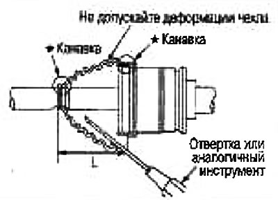
To avoid deforming the case, insert a screwdriver or similar tool under the case from the wide side and purge air from the case.
Cover installation length:
Wheel side:
AC1700i: 88.0 mm
AC2000i:91.0mm
AC2300i: 94.0 mm
From the gearbox side:
GI1700i: 89.4mm
GI2000i: 90.45mm
GI2300i: 91.5mm
Attention:
- If the installation length of the cover is different from the norm, the cover may break.
- Do not touch the inside of the case with the tip of the screwdriver.
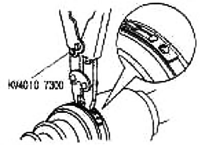
22. To prevent the cover from moving, hold the clip on the side opposite the bracket. Secure the wide side of the boot with a new clip as shown.
23. Make sure the boot clip is in the correct position by turning the boot. Otherwise, reinstall the boot with a new clip.
Attention: Fix the clip of the boot so that the gap «M» became equal to the one below.
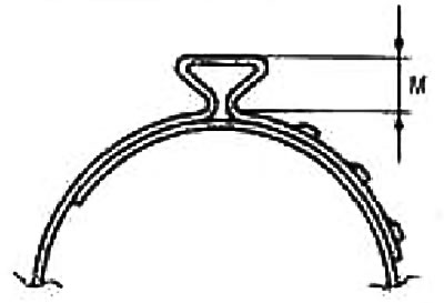
Wide side: 5mm
Narrow side: 5 mm
24. Make sure the drive shaft is still engaged with the differential.
25. Insert the drive shaft into the steering knuckle and tighten the locknut.
26. Tighten the bolts securing the steering knuckle to the rack. For tightening torques, see section «Front suspension».
27. Secure the brake hose to the strut with the retainer plate.
28. Press the tie rod onto the steering knuckle. For tightening torques, see section «Front suspension».
29. Install the ABS wheel sensor. See chapter Brake system.
30. Tighten the locknut to the required torque using a wrench (speinstrument)
Tightening torque: 280 Nm (29 kg m)
31. Install the wheels and lower the lift.