Check before disassembly
Move the hinge up/down, left/right and axially. Make sure the movement is smooth and there is no significant play.
Check for cracks and damage on the covers, and for leaks of grease.
Disassembly (on CR and HR16 engines)
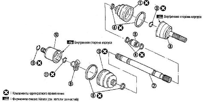
1. Case; 2. Ring clamp; 3. Hinge assembly (fixed hinge); 4. Case clip; 5. Dynamic shock absorber (only on the right side); 6. Clamp; 7. Shaft; 8. Case clip; 9. Cross assembly; 10. Case; 11. Retaining ring; 12. Body (sliding hinge); 13. Ring clamp
Gearbox Side
1. Remove the clips from the case.
2. Secure the shaft in a vise. Remove the case.
Attention: When fixing the shaft in a vise, protect it from damage by laying copper or aluminum plates. Do not clamp on the shock absorber area.
3. Place alignment marks on the shaft and spider assembly.
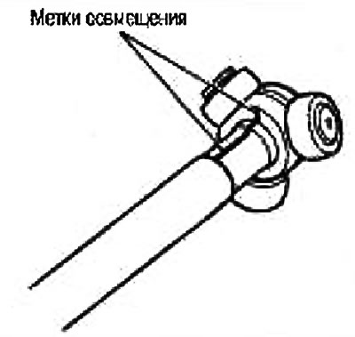
Caution: Mark with paint or similar. Do not scratch the surface.
4. Remove the retaining ring. Remove the cross assembly from the shaft. Use a bar to apply the load directly to the body of the spider assembly, not to the rollers.
5. Remove the cover from the shaft.
From the side of the wheel
1. Secure the shaft in a vise.
Attention: When fixing the shaft in a vise, protect it from damage by laying copper or aluminum plates. Do not clamp on the shock absorber area.
2. Remove the clips from the boot and remove the boot from the hinge assembly.
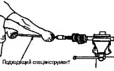
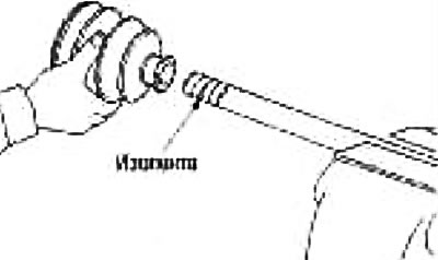
3. Screw on the drive shaft puller (suitable special tool) on the threads of the pivot assembly by at least 30 mm and remove the pivot assembly from the shaft.
Attention:
- Center the impact puller and drive shaft and remove with firm and even force.
- If the pivot assembly cannot be removed even after 5 attempts, replace the entire drive shaft assembly.
4. Remove the boot from the shaft.
5. Remove the ring clamp from the shaft.
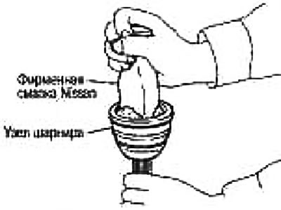
6. Wipe old grease off the pivot assembly with paper towels while rotating the yoke.
Caution: Perform a visual inspection to ensure there are no cuts, cracks, or kinks on the hinge assembly. Also check for debris from the road and metal debris in the lubricant. If abnormal, replace the pivot assembly as a set.
Dynamic shock absorber
Mark with paint the location of the shock absorber on the intermediate shaft. Remove the clamp. Then remove the dynamic damper from the shaft.
Check after disassembly (on CR and HR16 engines)
Shaft
If runout, cracks or damage is found, replace the shaft.
Hinge assembly (fixed hinge)
Check that the pivot assembly rotates freely and that there is no excessive end play.
Check for cuts, cracks, or kinks inside the hinge assembly.
Attention: If abnormality is found, replace the hinge assembly. Also check for debris from the road and metal debris in the lubricant.
Hinge assembly (sliding hinge)
If there are scratches or wear on the contact surface under the rollers on the body side or cross, replace the pivot assembly.
If there is peripheral play on the cross rollers or if they are binding, replace the pivot assembly.
If defects are found in the components, replace the hinge assembly.
Frame (sliding hinge)
Check for damage or excessive wear on the contact surface under the rollers.
Check for damage to the shaft threads.
Check if there is any deformation on the cover.
Dynamic shock absorber
Check for cracks or other damage. Replace if necessary.
Assembly (on CR and HR16 engines)
From the side of the wheel
Carry out the assembly by following paragraphs 13-22 of the section «Vehicle inspection and maintenance».
Dynamic shock absorber (right drive shaft)
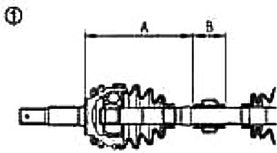
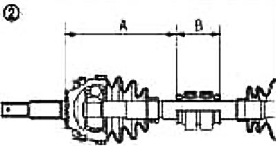
If the dynamic damper is removed, fix it with new clamps as shown in the figure so that the dimensions on the side of the fixed clamp correspond to those indicated.
Caution: Do not reuse the dynamic damper clips.
Size A:
On right (1): 434-440 mm
Left (2): 235-241 mm
Size H: 70 mm
Gearbox Side
1. To avoid damage to the boot during installation, wrap the spline of the drive shaft with electrical tape. Put a new boot and clamps on the shaft.
Attention: Do not reuse clips and case.
2. Remove the tape wrapped around the shaft spline.
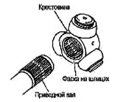
3. Align the paint marks made when removing the cross assembly. Install the cross assembly with the chamfer on the splines towards the drive shaft.
4. Secure the cross assembly with the circlip.
Caution: Do not reuse retaining ring.
5. Apply genuine Nissan grease to the pivot housing.
Amount of lubricant: 95-105g
6. Install the sliding joint housing onto the cross assembly.
7. Fit the case firmly into the grooves (marked with *), as it shown on the picture.
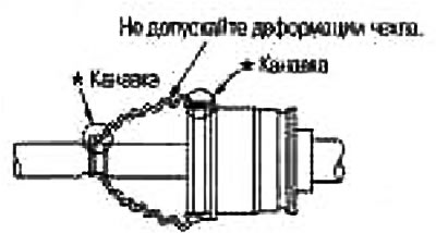
Attention: If the seating surfaces of the boot (marked with *) there is grease on the hinge, the cover may come off. Remove all grease from surfaces.
8. Attach the cover from the wide side as shown. Fully submerge the hinge so that the spider assembly is coated with grease. Pull the hinge back to the specified length. To avoid deforming the case, insert a screwdriver or similar tool under the case from the wide side and purge air from the case.
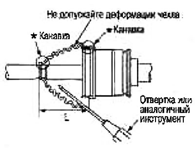
Cover installation length:
GI1700i: 89.4mm
Gl2000i: 90.45mm
Attention: If the installation length of the cover is different from the norm, the cover may break. Do not touch the inside of the case with the tip of the screwdriver.
9. Secure the narrow side of the boot with a new clip as shown.
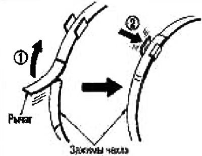
Attention: Rotate the hinge body and make sure that the cover does not come off from its place. Otherwise, reinstall boot clips.