


Table of contents: Removal ↓ Check after removal ↓ Installation ↓ Post-installation check ↓ Check table ↓ Checking the oil groove on the…↓
Note: The direction of rotation indicated in the text refers to the rotation as viewed from the front of the engine.
Removal
Note: This section describes the procedure for removing and installing the camshaft with the front cover. If the front cover is removed first, reverse the order of the following steps:
- p 8: After removing the camshaft sprocket, remove the camshaft brackets (Nos. 2-5).
- p 9: The exhaust camshaft can be removed simultaneously with the intake camshaft.
- p 10: When unscrewing the intake camshaft mounting bolt, it is not necessary to lift the camshaft.
1. Support the bottom of the engine with a telescopic strut, then remove the bracket and insulator from the right engine mount. See Section "Engine assembly".
2. Remove the valve cover. See section "Valve cover".
3. Remove the camshaft angle sensor (PHASE) from the back of the cylinder head.
Caution: Handle the sensor with care, do not drop or hit it.
4. Set the piston of cylinder No.1 to TDC in the compression stroke as follows:
- a. Turn the crankshaft pulley (2) clockwise and align the timing mark (colorless risk) (A) with timing indicator (1) on the front cover.
- b. Make sure that the alignment marks on the camshaft sprockets are aligned as shown in the illustration.

B. Mark with white paint (not used for maintenance)
Otherwise, rotate the crankshaft pulley one more revolution and align the marks as shown in the figure
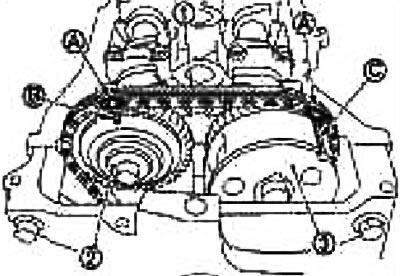
1. Timing chain; 2. Exhaust camshaft sprocket; 3. Intake camshaft sprocket; A. Alignment mark (paint); B. Alignment mark (stamped); C. Alignment mark (risk carved on the periphery)
- c. Apply alignment marks (A) to the timing chain links with paint
5. Fix the chain tensioner plunger in the fully compressed position as follows. Then release the timing chain tension
- a. Remove the plug (2) from the front cover (1)
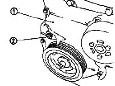
- b. Fully push the chain tensioner lever (B) (2) through the plug hole and insert the lock pin (A) into the hole in the tensioner body and lock the lever in the lower position.
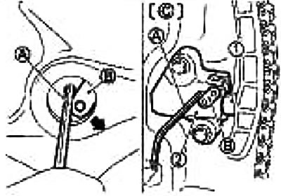
C. Front cover not shown
The plunger locking tongue (1) can be released by fully pressing the lever (coaxial with lever design). As a result, the plunger can be moved.
Note: A hex wrench (2.5mm) is used instead of a lock pin as an example.
Caution: The locking pin must be shaped so that it will not fall into the front cover if it falls out.
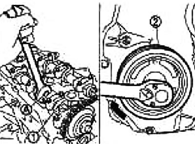
- c. Turn the crankshaft pulley (2) counterclockwise, locking the exhaust camshaft (1). Tighten the timing chain and press the plunger into the chain tensioner.
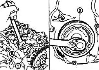
Caution: Secure the camshaft by the hexagonal part (A) so that it cannot turn.
- d. Remove the lock pin (A) of the chain tensioner (2) from the plug hole. Raise the lever (B) and align the hole in it with the hole in the housing.
By aligning the holes in the lever (C) and the body, the plunger (1) can be fixed.
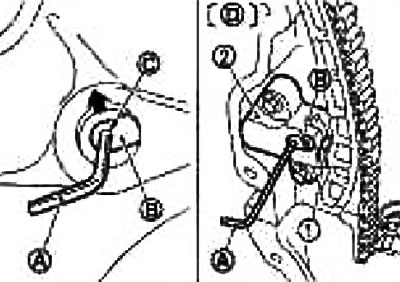
D. Front cover not shown
When the protruding parts of the plunger ratchet and the locking tongue face each other, the holes are not aligned. Engage them correctly and align these holes by moving the plunger slightly.
- e. Insert the lock pin into the hole in the tensioner body through the hole in the lever and lock the lever in the upper position.
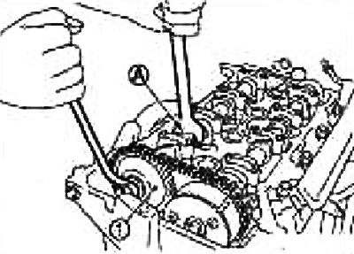
- f. Turn the crankshaft pulley (2) slightly clockwise and loosen the timing chain on the exhaust camshaft sprocket side (1) (see fig below).
Caution: Secure the camshaft by the hexagonal part (A) so that it cannot turn.
6. Remove the exhaust camshaft sprocket (1)
Attention:
- Secure the camshaft by the hexagonal part (A) so that it cannot turn.
- After removing the timing chain, do not turn the crankshaft or camshaft separately, otherwise the valves will hit the piston crowns.
Note: The timing chain with the front cover installed does not disengage from the crankshaft sprocket and does not fall into the front cover. Therefore, a timing chain tensioner is not required.
7. Turn the intake camshaft sprocket to the maximum advance position.
Attention:
- Removal and installation the intake camshaft sprocket in the maximum advance position is required for the following reasons. Therefore, perform the procedure exactly as indicated below.
- This model uses a design in which the star (C) and blade (together with the camshaft joint) (B) rotate and shift relative to each other at some given angles.
- When the engine is stopped, the blade is in the maximum retard position. It does not rotate because it is locked in the sprocket by an internal locking pin (A).
- If you turn the camshaft sprocket mounting bolts under the specified conditions, you will apply a lateral load (shear force) to the locking pin. This will damage the locking pin and cause the mechanism to malfunction.
Set the intake camshaft sprocket to the maximum advance position as follows:
- a. Remove the camshaft bracket (Nel) (1)
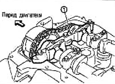
Loosen the bolts in several passes and unscrew them.
- b. Using a pneumatic gun, apply pressure to the lubrication hole of journal No.1 (A) of the intake camshaft (1).
Air pressure: 300 kPa (3.1 kg/cm²) or more
Apply pressure to the oil hole in the second groove from the front thrust surface (B) of the camshaft.
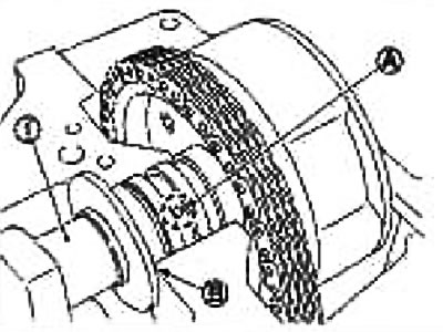
Maintain pressure until step "e" is completed.
To prevent air from leaking from the grease hole, press the rubber tip (B) tapering toward the end of the air gun (A) Securely apply pressure to the grease hole.
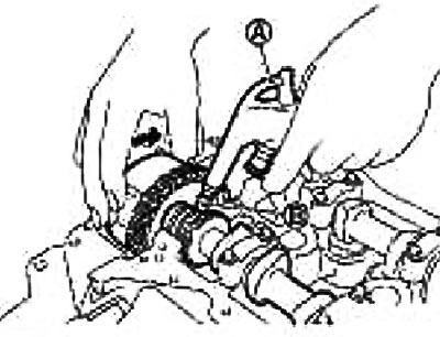
Attention:
- There are other lubrication holes in the side grooves. Do not confuse them.
- Do not damage the grease channel with the gun tip.
- To avoid blowing oil in with the air, carefully wipe the oil off the gun and wipe the oil off with a rag from the area adjacent to the gun when applying pressure. Wear safety glasses if necessary.
Note: The locking pin is held in the unlocked position by compressed air.
- c. Grasp the intake camshaft sprocket with your hands and apply force alternately counterclockwise/clockwise.
Finally, turn the intake camshaft sprocket counterclockwise in the direction indicated by the arrow.
Perform the operation by supplying compressed air to the lubrication hole.
If the locking pin does not release by hand, lightly tap the intake camshaft sprocket with a plastic hammer (A).
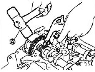
If the intake camshaft sprocket does not turn counterclockwise even when the above operation is performed, check the air pressure and the position of the oil hole.
- d. While performing the above operation, you will hear a clicking sound from inside the intake camshaft sprocket (sound indicating that the internal locking pin has come out of engagement). When you hear this sound, slowly turn the intake camshaft sprocket counterclockwise to the maximum advance position.
Perform the operation by supplying compressed air.
If the blade part (together with the camshaft joint)one rotates relative to the sprocket, then the locking pin has come out of engagement, even if the click is not heard.
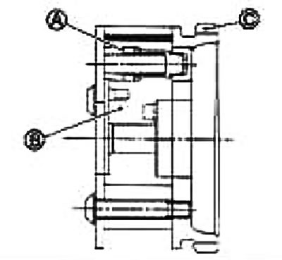
Make sure that the sprocket has reached the maximum lead position by checking whether the locking pin groove (A) and the locking pin hole (B) are aligned, as shown in the figure below).
- e. Stop supplying compressed air and holding the intake camshaft.
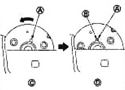
C. Locking pin engaged D. Maximum advance position
- f. Insert the lock pin (A) into the holes in the intake camshaft sprocket and fix it at the maximum advance position.
Attention: Load (spring reaction force, etc.) does not apply to the locking pin and it can easily fall out. Therefore, secure it with vinyl tape (B).
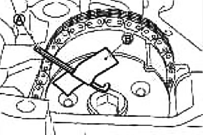
Note: As an example, a hex wrench (2.5mm) is used instead of a locking pin (length of inserted section approx. 15 mm).
8. Remove the camshaft brackets (Nos. 2-5).
Loosen the mounting bolts in several passes in the reverse order to that shown in the illustration.
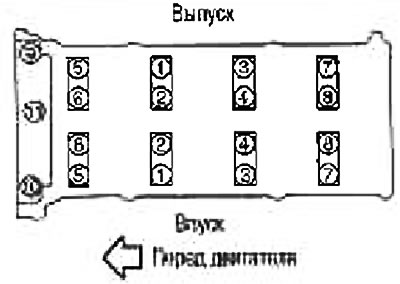
Note: The camshaft bracket (No. 1) has already been removed.
9. Remove the exhaust camshaft.
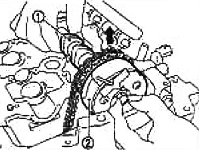
10. Remove the intake camshaft (1) and intake camshaft sprocket (2) as follows:
- a. Lift the intake camshaft sprocket and apply a flat tool (open-end wrench, etc) on the mounting bolt (A).
- b. Carefully lower the intake camshaft onto the cylinder head journals.
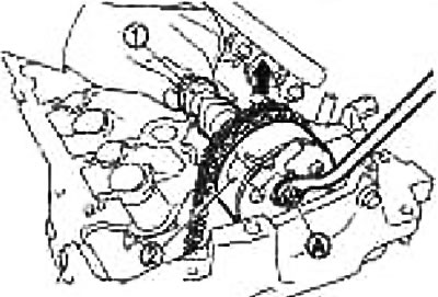
- c. While continuing to hold the hexagonal portion of the camshaft (A) with an adjustable wrench, loosen the intake camshaft sprocket mounting bolts (2).
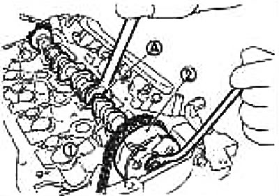
1. Intake camshaft
- d. Lift the intake camshaft (1) and separate it from the sprocket (2).
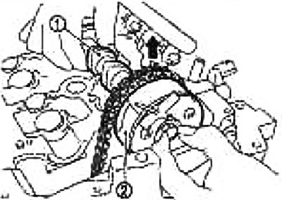
- e. Remove the intake camshaft in a rearward direction.
Caution: Do not damage the signal disc on the rear end.
- f. Remove the intake camshaft sprocket (1).
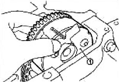
Attention:
- Do not drop the locking pin.
- To prevent the locking pin (B) from falling out, secure it with vinyl tape (C).
- Handle the camshaft sprocket with care, do not hit it or drop it.
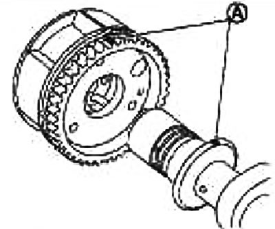
- Do not disassemble the sprocket. [Do not loosen the three bolts (A) on the front surface].
![Do not disassemble the sprocket. [Do not loosen the three bolts (A) on the front surface].](https://www.nissanbook.ru/img/variant/0858.jpg)
Note: If, during removal of the intake camshaft sprocket, when you remove the locking pin and the locking pin engages in the maximum retard position, restore the original position as follows:
- i. Install the intake camshaft sprocket back onto the camshaft and tighten the mounting bolts to prevent air leakage.
Caution: To avoid damage to the internal locking pin, the tightening torque of the mounting bolts must be as low as possible to avoid air leakage.
- ii. Apply compressed air, disengage the locking pin and rotate the blade to the maximum advance position.
- iii. Insert the locking pin.
- iv. Remove the sprocket from the camshaft.
11. Remove the valve lifters.
Mark the locations and place the components in order without mixing them.
12. Remove the intake valve timing control solenoid valve (1).
13. Remove the generator and bracket, unscrew the plug (2) and remove the oil filter. See chapter Electrical equipment.
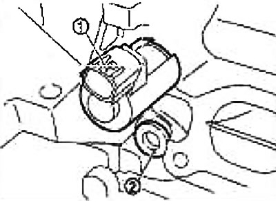
Check after removal
Oil filter
Make sure that there are no foreign particles on the oil filter (1) and check if it is clogged.
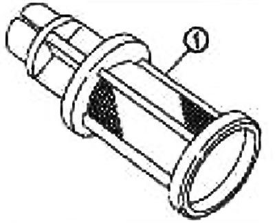
Check the oil filter for damage.
If there is damage, replace the oil filter, plug and washer as a set.
Camshaft runout
1. Install the camshaft on two prisms with journals No.2 and No.5.
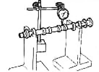
Caution: Do not install the camshaft on the prisms with journal No.1 (from the camshaft sprocket side), because its diameter differs from the other four.
2. Fix the sensitive head of the indicator vertically on the neck No.3.
3. Turn the camshaft manually in one direction and measure the runout with a dial indicator, (maximum indicator reading).
| Standard | 0.02 mm |
| Limit | 0.1 mm |
4. If the runout exceeds the limit, replace the camshaft.
Camshaft lobe height
1. Measure the camshaft lobe height with a micrometer (A).
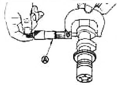
| Standard | |
| Inlet | 41.705-41.895 mm |
| Release | 40.175-40.65 mm |
| Cam wear limit | 0.2 mm |
If the height is different from the norm, replace the camshaft.
Oil clearance in camshaft journals
Camshaft journal outside diameter Measure the camshaft journal outside diameter with a micrometer (A).
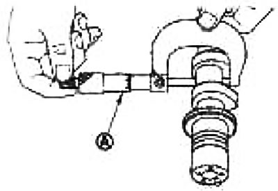
| Standard | №1 | 27,935-27,955 mm |
| №№2,3,4,5 | 24,950-24,970 mm |
Inner diameter of camshaft bracket
Tighten the camshaft bracket bolts to the specified torque. Refer to the Installation section for tightening torques.
Measure the inside diameter (B) of the camshaft bracket with a bore gauge (A).
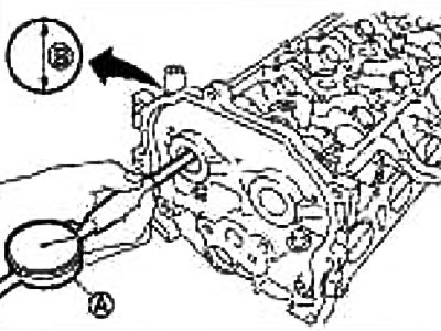
| Standard | №1 | 28,000-28,021 mm |
| № 2,3,4,5 | 25,000-25,021 mm |
Calculation of oil clearance in camshaft journals
(Oil clearance in journals) = (camshaft bracket inner diameter) - (camshaft journal outer diameter)
| Standard | №1 | 0.045-0.086 mm |
| №№ 2,3,4,5 | 0.030-0.071 mm | |
| Limit | 0.15 mm |
If the obtained value is different from the norm, replace either the camshaft or the cylinder head, or both.
Note: The camshaft brackets are integral with the cylinder head. Replace the cylinder head as an assembly.
Camshaft axial play
1. Install the camshaft into the cylinder head. For tightening torques, see section "Installation".
2. Set the indicator (A) axially with the sensitive head against the front end of the camshaft. Measure the axial play by moving the camshaft forward/backward (in the axial direction).
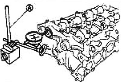
| Standard | 0.075-0.153 mm |
| Limit | 0.2 mm |
If the axial play is different from the norm, measure the dimensions of the following components:
- Cylinder Head Bearing No.1 A Size Standard: 4.000-4.030mm
- Camshaft thrust surface dimension "B". Standard: 3.077-3.925 mm
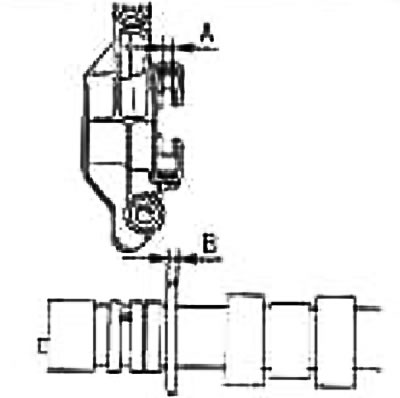
Compare the measurement results with the standard values specified above and replace the camshaft and/or cylinder head.
Camshaft Sprocket Runout
1. Install the camshaft on two prisms with journals No.2 and No.5.
Caution: Do not install the camshaft on the prisms with journal No.1 (from the camshaft sprocket side), because its diameter differs from the other three.
2. Measure the camshaft sprocket runout with a dial indicator (maximum indicator reading).
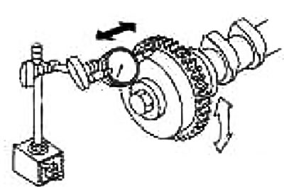
Limit: 0.15 mm
If the runout exceeds the limit, replace the camshaft sprocket.
Valve tappet
Check the valve lifter surface for wear or chipping.
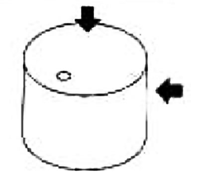
If any defects are found, replace the valve lifter.
Valve tappet clearance
Valve tappet outer diameter.
Measure the outside diameter with a micrometer (A) (see fig.).
Standard: 29.977-29.987 mm
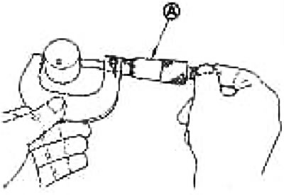
Valve tappet hole diameter.
Measure the diameter of the valve tappet hole in the cylinder head using a bore gauge (A).
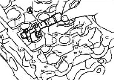
Standard: 30,000-30,021 mm.
Calculating valve tappet clearance
(Valve tappet clearance) = (valve tappet hole diameter) - (valve tappet outer diameter)
Standard: 0.013-0.044 mm
If the obtained value differs from the standard for both the inside and outside diameters, replace either the valve lifter or the cylinder head, or both.
Installation
1. Insert the oil filter (1).
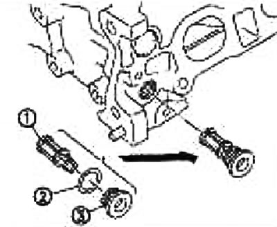
2. Washer
The oil filter is inserted into the plug (3) and then into the cylinder head.
2. Install the intake valve timing control solenoid valve.
Insert it into the cylinder head at a right angle.
Once the valve is fully inserted, tighten the bolts.
3. Install the valve lifters.
If reusing, install them in the same locations they were in before removal.
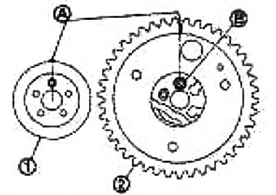
4. Apply alignment marks for installing the intake camshaft and intake camshaft sprocket as follows:
Note: This operation is intended to prevent the guide protrusion from entering an unintended hole after the intake camshaft and intake camshaft sprocket have been installed.
- a. Apply alignment marks (A) at right angles from the guide lug position on the front surface of the intake camshaft (1).
Apply marks on a visible area with the intake camshaft sprocket installed (The figure shows an example).
- b. Make alignment marks at right angles from the position of the guide lug hole (B) on the intake camshaft sprocket (2). (The figure shows an example).
5. Install the intake camshaft sprocket between the cylinder head and the front cover.
Install it with the hole for the guide lug (A) facing up.
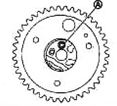
Caution: Make sure that the locking pin is inserted in the maximum advance position in advance.
6. Install the camshafts.
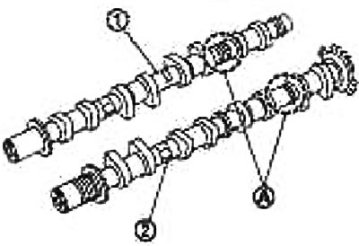
1. Exhaust camshaft
2. Intake camshaft
A. Distinctive markings
The intake and exhaust camshafts can be distinguished by the shape of their rear ends.
Install the camshafts into the cylinder head so that the guide lugs (A) on the front ends are positioned as shown in the illustration.
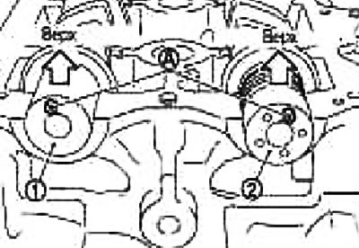
1. Exhaust camshaft
2. Intake camshaft
Note: Although the camshaft does not stop in the position shown in the illustration for installing the cam lobes, it is generally acceptable for the camshaft to be installed in the same direction as shown.
7. Install the intake camshaft sprocket onto the intake camshaft as follows:
- a. Use the alignment mark (A) applied in step 4 as a guide. Align the guide protrusion and the hole for it and connect them.
- b. Raise the front side of the intake camshaft (1) and tighten the bolt by hand.
2. Intake camshaft sprocket.
8. Place a thick cloth (B) underneath and place the tool on the bolt (A) while lifting the front side of the intake camshaft.
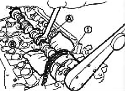
9. Tighten the mounting bolt.
Caution: Secure the camshaft by the hexagonal part (A) so that it cannot turn.
10. Carefully lower the intake camshaft onto the cylinder head journals.
11. Put on the timing chain (1), aligning the mark (applied to it when removed) (B) with the label (with a risk carved on the periphery) (A) on the intake camshaft sprocket (2).
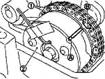
12. Install the camshaft brackets (Nos. 2-5), using the distinctive markings stamped on the upper surface as a guide.
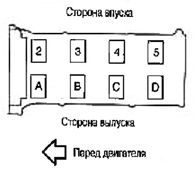
Install so that the distinctive markings are legible correctly when viewed from the intake side.
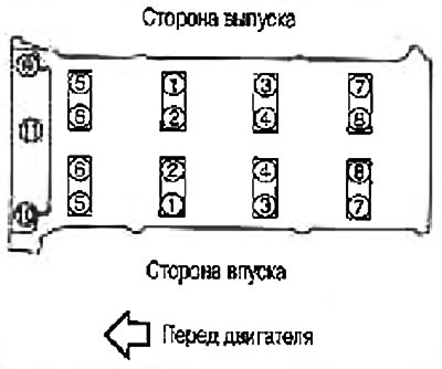
13. Tighten the camshaft bracket mounting bolts in the order shown by the numbers in the illustration as follows:
- a. Tighten in order from 9 to 11.
Tightening torque: 2.0 Nm (0.2 kg·m)
- b. Tighten in order from 1 to 8.
Tightening torque: 2.0 *m (0.2 kg·m)
- c. Tighten all bolts in the order indicated by the numbers in the figure.
Tightening torque: 5.9 Nm (0.6 kg·m)
- d. Retighten all bolts in the order shown by the numbers in the figure.
Tightening torque: 10.4 Nm (1.1 kg·m)
14. Install the exhaust camshaft into the sprocket (2), aligning the mark (applied to it when removing the timing chain) (A) with a mark (stamped) (B) on the exhaust camshaft sprocket.
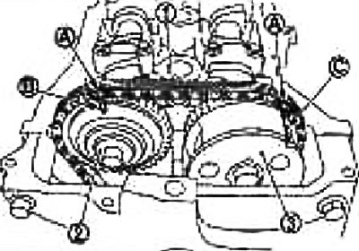
1. Timing chain
3. Exhaust camshaft sprocket
C. Alignment mark (risk carved into the periphery)
If the positions of the guide protrusion and the groove for it are not aligned, slightly rotate the exhaust camshaft and align it
15. Tighten the mounting bolt.
Caution: Secure the camshaft by the hexagonal part (A) so that it cannot turn. Make sure that the marks on the intake and exhaust camshaft sprockets are aligned (applied to them when removing the timing chain) aligned with the marks on the timing chain.
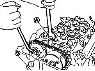
1. Exhaust camshaft sprocket.
16. Remove the locking pin (A) and tighten the timing chain by turning the crankshaft pulley slightly clockwise.
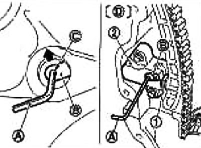
1. Plunger
2. Chain tensioner
V. Lever
C. Hole for lever
D. Front cover not shown
17. Screw the plug (2) into the front cover.
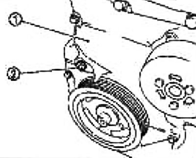
Apply thread sealant to the threads and screw in.
Use brand name sealant or equivalent.
18. Return the intake camshaft sprocket to the maximum retard position as follows:
- a. Remove the lock pin (A) from the intake camshaft sprocket.
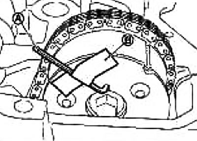
V. Tape
- b. Slowly turn the crankshaft pulley (1) clockwise (A) and return the intake camshaft sprocket to the maximum retard position.
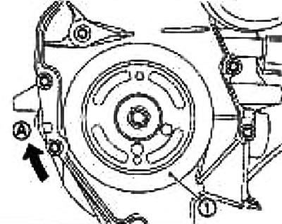
When the crankshaft is first rotated, the sprocket starts to rotate. Continue rotating the crankshaft until the blade also starts to rotate (camshaft), and the position of maximum delay is reached.
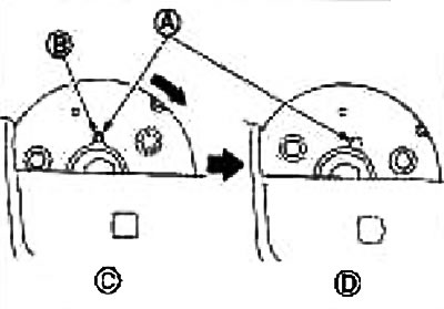
B. Hole for locking pin
C. Position of maximum lag
D. The locking pin has engaged
You can check whether the maximum lag position has been reached by seeing if the groove (A) for the locking pin has moved clockwise.
Original text on the website [www.NissanBook.ru]
By turning the crankshaft slightly counterclockwise, you can be sure that the locking pin has engaged if you see that the blade (camshaft) and the star rotate together.
19. Install the camshaft angle sensor (PHASE) to the rear end of the cylinder head.
Tighten the bolts, making sure the sensor is fully seated in the mounting hole.
20. Check and adjust valve clearances. See the Valve Clearances section.
21. After this operation, installation is carried out in the reverse order of removal.
Post-installation check
Checking for leaks
Below are procedures for checking for fluid, engine oil and exhaust leaks.
Before starting the engine, check the oil/fluid levels, including engine coolant and engine oil. If the level is low, top up to the required level. See chapter General information and maintenance.
Check for fuel leaks as follows:
- Turn the ignition key to the "ON" position (without starting the engine) After pressurizing the fuel lines, check for fuel leaks at the joints.
- Start the engine. Increase the engine speed and check again for fuel leaks at the fuel line joints
Let the engine run and check for any unusual noise or vibration.
Note: If the hydraulic pressure inside the timing chain tensioner drops after removal/installation, a dull knocking sound may occur when the engine is started and immediately after the slack in the guide may result. However, this does not indicate a malfunction. The knocking sound will stop after the hydraulic pressure rises.
Warm up the engine thoroughly and check for any fuel, exhaust or oil/fluid leaks, including engine coolant and engine oil.
Bleed air from the pipes and hoses of the relevant systems, such as the cooling system.
After the engine has cooled down, check the oil/fluid levels again, including engine coolant and engine oil. Top up as necessary to the proper level.
Check table
| Component | Before starting the engine | With the engine running | After the engine has stopped |
| Engine coolant | Level | Leakage | Level |
| Motor oil | Level | Leakage | Level |
| Other oils and liquids* | Level | Leakage | Level |
| Fuel | Leakage | Leakage | Leakage |
| Exhaust gases | - | Leakage | - |
*Fluid for manual transmission, automatic transmission, brake fluid, etc.
Checking the oil groove on the intake camshaft sprocket
Caution: To avoid burns from engine oil splashes, perform the check when the engine is cold.
1. Check the engine oil level. See chapter Lubrication system and engine cooling system.
2. Perform the following procedure to avoid accidental engine starting during the test.
- a. Relieve the fuel pressure. See chapter Engine management system.
- b. Remove the upper portion of the intake manifold. See section "Upper part of the intake manifold".
- c. Disconnect the connectors from the ignition coils and injectors.
3 Remove the intake valve timing control solenoid valve. See section "Camshaft".
4. Crank the engine and check whether engine oil flows out from the oil hole (A) of the intake valve timing cover. Stop cranking after checking.
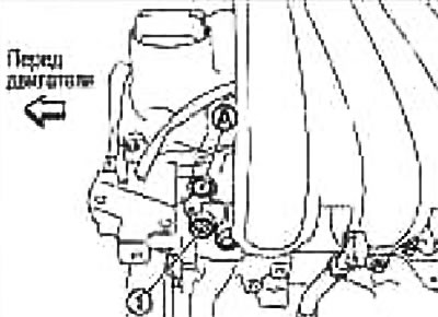
1. Plug
Attention:
- Do not touch rotating components (drive belts, tension pulley and crankshaft pulley, etc.).
- To prevent oil from splashing on a person and causing burns, as well as dirt getting into the oil, use a napkin.
- Use a cloth to protect engine and vehicle components from oil. Avoid allowing engine oil to come into contact with rubber parts such as the drive belt or engine mount insulators. Wipe up any spilled engine oil immediately.
5. If engine oil does not flow out of the oil hole of the intake valve timing cover in the cylinder head, perform the following check.
Remove the oil filter and clean it. See chapter Lubrication system and engine cooling system.
Clean the lubrication groove between the coarse filter and the intake valve timing control solenoid valve. See section "Oil filter".
6. Remove the components between the intake camshaft timing solenoid valve and the intake camshaft sprocket and check whether the oil grooves are clogged.
If necessary, clean the oil groove. See chapter Lubrication system and engine cooling system.
7. After checking, install the removed components in the reverse order of removal.