Note. A description of the condition check, as well as adjusting the tension of the auxiliary drive belts, is given in Section Checking the condition of the accessory drive belt and adjusting its tension.
Idler Roller Installation Components
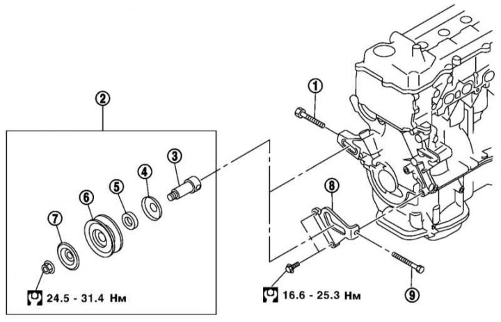
1 - Adjusting bolt of the water pump drive belt; 2 - Assembly of the intermediate roller; 3 - Axis; 4, 7 - Cover; 5 - Bushing; 6 - Intermediate pulley; 8 - Bracket; 9 - Adjusting bolt of a belt of a drive of the generator and compressor K/V
1. Fully loosen each belt (see Section Checking the condition of the accessory drive belt and adjusting its tension) and remove the belts, starting from the front.
Note. If the belt is removed not for the purpose of replacement, mark on it the direction of its movement.
2. The installation components of the intermediate rollers of the belts are shown in the illustration above.
3. To remove the intermediate pulley of the alternator drive belt and the K / V compressor, remove the adjusting bolt from the pulley axis, slide the pulley along the groove on the bracket and remove by turning the end of the axis on the widest part of the groove.
4. To remove the water pump drive belt idler pulley, loosen the locknut and remove the axle by pulling it towards the rear of the engine.
5. Installation of pulleys is made upside-down.
6. Check that both the belts and the pulleys are free of grease, oil or coolant and install the belts. If a belt that has already been used is installed, observe the direction of its movement.
7. Make sure the belts are correctly positioned in the grooves of the pulleys.
8. Rotate the crankshaft at least two turns to even out the belt tension between the various pulleys. Check and, if necessary, adjust the tension of the belts (see Section Checking the condition of the accessory drive belt and adjusting its tension).