


Exhaust Manifold and Catalytic Converter Mounting Components
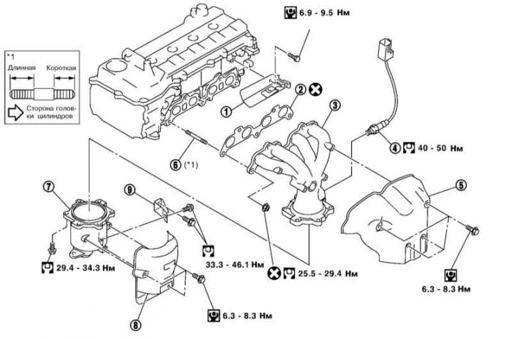
1, 9 - Bracket; 2 - Gasket; 3 - Exhaust manifold; 4 - Lambda probe No.1; 5 - Exhaust manifold heat shield; 6 - Hairpin; 7 - 3-function catalytic converter; 8 - Catalytic converter heat shield
1. Remove the air intake sleeve (see section Removal and installation air intake tract components) and the right front right wheel arch liner (see Chapter Body).
2. Remove the generator and A/C compressor drive belt (see section Replacement of auxiliary drive belts and intermediate belt rollers).
3. Remove the air conditioning compressor without disconnecting the tubes from it, move the compressor to the side and secure it with a rope to the body elements so that the tubes are not loaded.
4. Separate the front connection of the front section of the exhaust pipe (see Chapter Fuel and exhaust systems) and remove the right engine mount stand and the generator bracket.
5. Loosen the lower bolt and move the generator towards the front of the vehicle.
The original is posted on the portal: nissanbook.ru
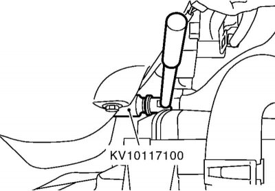
6. If necessary, remove lambda probe No.1 by disconnecting its connector, removing the connector from the bracket and unscrewing the lambda probe using a special key.
Note: When removing only the lambda probe, it is sufficient to first remove the air intake sleeve. Do not subject the lambda probe to impacts, do not drop it, and do not overtighten it when installing.
7. Remove the exhaust manifold and catalytic converter heat shields.
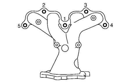
8. Remove the nuts and bolts in the reverse order to that shown in the accompanying illustration.
Note: Do not damage the A/C system tubes.
9. Separate the exhaust manifold and catalytic converter from each other.
10. Using a steel ruler and a blade-type feeler gauge, measure the non-flatness of the mating surface of the exhaust manifold and compare the result with the requirements Specifications. Replace the exhaust manifold if necessary.
11. Installation is carried out in the reverse order. Pay attention to the cleanliness of the mating surfaces. Tighten the fasteners in the sequence shown in the illustration above. Do not overtighten the lambda probe to avoid damage.