


Table of contents: Removal and installation ↓ Check after removal ↓
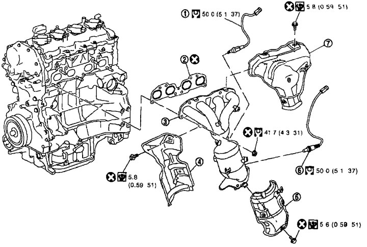
Exhaust manifold and three-way catalytic converter 1. Heated oxygen sensor 1; 2. Gasket; 3. Exhaust manifold and three-way catalytic converter assembly; 4. Three-way catalytic converter cover; 5. Exhaust manifold cover (lower); 6. Heated oxygen sensor 2; 7. Exhaust manifold cover (upper).
Removal and installation
Removal
1. Remove the heated oxygen sensors as follows:
- a. Disconnect the connectors from the heated oxygen sensors and remove the wiring from the bracket and center clamp.
- b. Remove the heated oxygen sensors using the heated oxygen sensor wrench (special tool).
(Text duplicated from the website: nissanbook.ru)
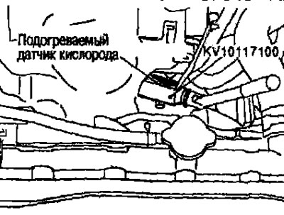
Attention:
- Do not damage the heated oxygen sensor.
- Discard the heated oxygen sensor if it is dropped on a hard surface, such as a concrete floor. Replace it with a new one.
2. Disconnect the front exhaust pipe. See chapter "Accelerator, fuel system and exhaust system".
3. Remove the generator. See chapter "Electrical equipment".
4. Remove the top cover from the exhaust manifold.
5. Loosen the nuts in the reverse order shown in the illustration and remove the exhaust manifold and three-way catalytic converter assembly.
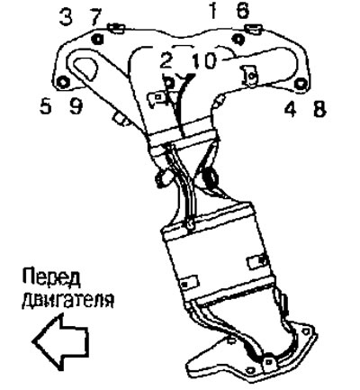
Note: Ignore #6-10 when loosening.
6. Remove the gasket.
Caution: To prevent foreign particles from entering, plug the openings in the engine.
7. Remove the lower cover from the exhaust manifold and the catalytic converter cover from the exhaust manifold and three-way catalytic converter assembly.
Installation
Installation is carried out in the reverse order of removal, taking into account the following:
Exhaust manifold
- If the studs were unscrewed, screw them back in and tighten them to the required torque
 . 14.7 N·m (1.5 kg·m)
- Tighten the nuts in the order indicated by the numbers in the figure
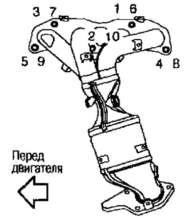
Note: Nos. 6-10 mean double tightening of bolts Nos. 1 and 5.
Heated oxygen sensors
Attention:
- Before installing a new heated oxygen sensor, clean the threads in the exhaust system using a heated oxygen sensor thread cleaner (suitable special tool) and apply anti-seize compound.
- Do not overtighten the heated oxygen sensor, otherwise the sensor may be damaged, which will cause the "M1" malfunction indicator to illuminate.
Check after removal
Surface warping
Using a ruler (A) and feeler gauge (B), check whether the contact surface of the exhaust manifold is warped.
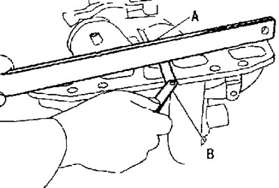
Limit: See below section "Technical data and specifications"
- If the warpage exceeds the limit, replace the exhaust manifold.