


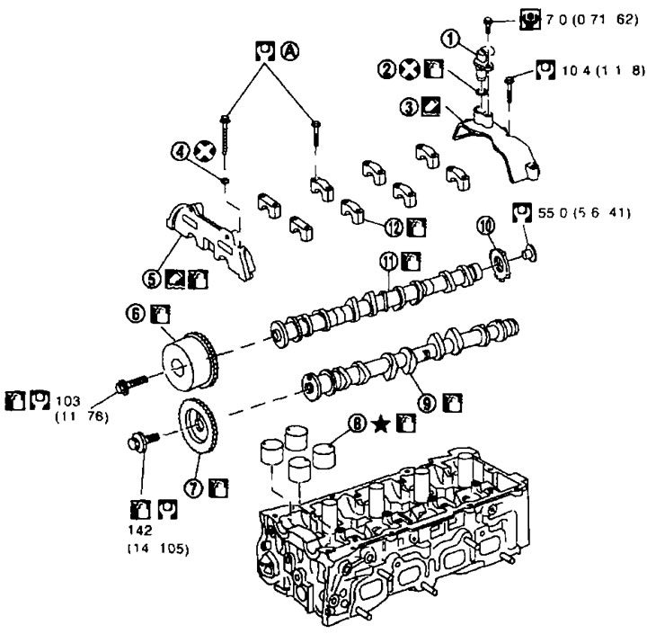
1. Camshaft angle sensor (PHASE); 2. O-ring seal; 3. Bracket of the camshaft angle sensor; 4. Sealing washer; 5. Bracket (No. 1) of camshafts; 6. Camshaft sprocket (intake); 7. Camshaft sprocket (outlet); 8. Valve tappet; 9. Camshaft (exhaust); 10. Signal disk; 11. Camshaft (intake); 12. Brackets (N°N°2-5) of camshafts; A. See below.
Removal and installation
Removal
Note: This section describes the procedure for removing and installing the camshaft without removing the front cover. If the front cover is crushed or installed, it is better to remove the camshaft bracket (No. 1) before step 9 and install it after step 4. For the operations for removing and installing the front cover, see below in step "Timing Chain".
1. Relieve the fuel pressure. See chapter "Engine management system".
2. Remove the following components:
3. Remove the camshaft angle sensor (PHASE).
Attention:
- Handle the sensor with care, do not drop or hit it.
- Do not disassemble the sensor.
- Avoid allowing metal powder to come into contact with the magnetic portion of the sensor tip.
- Do not leave the sensor in places where it may be exposed to magnetism.
4. Remove the camshaft angle sensor bracket.
- Loosen the mounting bolts in the reverse order to that shown in the illustration.

5. Remove the cover from the intake valve timing mechanism as follows:
a. Disconnect the connector from the intake valve timing control solenoid valve.
b. If necessary, remove the intake valve timing control solenoid valve.
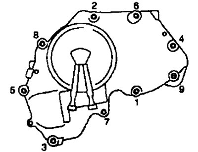
c. Loosen the bolts in the reverse order to that shown in the figure.
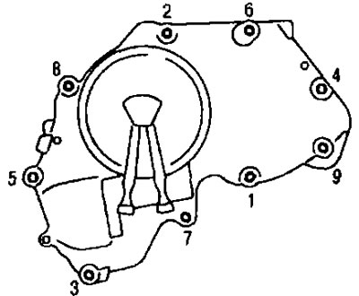
d. Cut off the sealant with a cutter (special tool: KV10111100) or equivalent tool and remove the cover.
6. Remove the timing chain guide between the camshaft sprockets through the front cover.
7. Set the piston of cylinder No.1 to TDC in the compression stroke as follows:
a. Remove the mudguard on the right side.
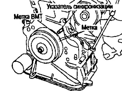
b. Turn the crankshaft pulley clockwise and align the TDC mark with the timing indicator on the front cover.
c. At the same time, make sure that the alignment marks on the camshaft sprockets are positioned as shown in the figure.
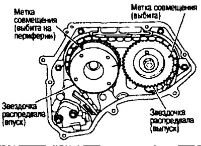
- Otherwise, rotate the crankshaft pulley one more revolution and align the marks as shown in the figure.
8. Remove the camshaft sprockets as follows:
a. Apply permanent paint to the timing chain link linings opposite the marks on the camshaft sprockets.
b. Press the plunger of the chain tensioner. Insert the locking pin into the hole in the tensioner body, lock the plunger and remove the chain tensioner.
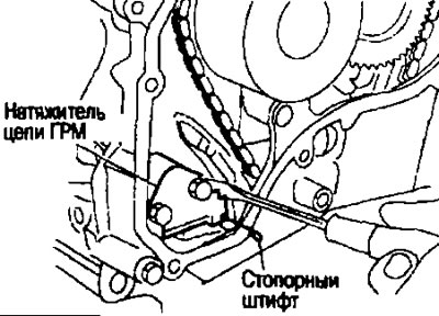
Note: A metal rod with a diameter of approximately 0.5 mm can be used as a locking pin.
c. Secure the camshaft by the hexagonal part with a wrench. Loosen the camshaft sprocket mounting bolts and remove the sprockets.
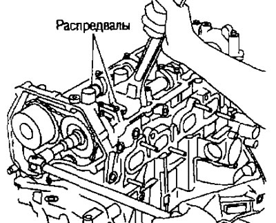
Caution: After removing the timing chain, do not turn the crankshaft or camshafts separately, otherwise the valves will hit the piston crowns.
Note: There is no need to maintain chain tension. The crankshaft sprocket and timing chain are not separated by design when installing the front cover.
9. Loosen the mounting bolts and nuts in the reverse order to that shown in the illustration and remove the camshaft brackets and camshafts.
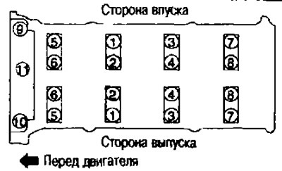
- Remove the camshaft bracket (No. 1) by lightly tapping it with a plastic hammer.
10. Remove the valve lifters.
- Mark the locations and stack the components in order without mixing them.
Installation
1. Install the valve lifters.
- Install them in the same places they were before removal.
2. Install the camshafts.
- The intake and exhaust camshafts can be distinguished by the shape of their rear ends.
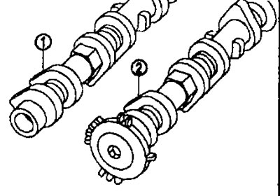
1. Camshaft (exhaust).
2. Camshaft (intake).
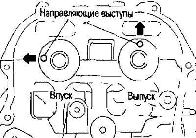
- Install the camshafts so that the guide tabs on the front ends are positioned as shown in the figure.
3. Install the camshaft brackets as follows:
a. Completely remove foreign particles from the back side of the camshaft bracket and from the mounting surface in the cylinder head.
b. Install the camshaft brackets (No. 2-5) according to the identification marking stamped on the upper surface, as shown in the figure.
(Read more on the website: «nissanbook»)
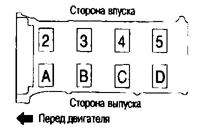
Note: Install so that the identification marking can be read correctly when viewed from the outlet side.
c. Install the camshaft bracket (No. 1) as follows:
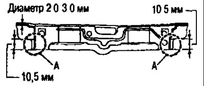
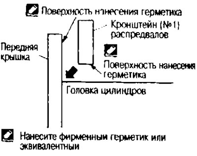
I. Apply sealant to the camshaft bracket (No. 1) as shown in the figure. Use the original sealant or equivalent.
Note: After installation, remove any protruding sealant from section "A".
II. Apply sealant to the contact surface under the camshaft bracket (No. 1) on the back of the front cover.
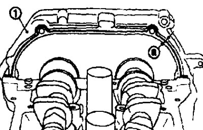
1. Front cover
a. 3.4-4.4 mm
Use brand name sealant or equivalent.
- Apply sealant to the outside of the bolt holes on the front cover.
III. Install the camshaft bracket (No. 1) so that the sealant applied to the surfaces does not shift.
4. Tighten the camshaft bracket mounting bolts in several passes in the order indicated by the numbers in the figure:
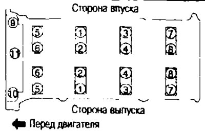
a. Tighten in order from #9 to #11.
 : 2.0 N·m (0.2 kg·m)
b. Tighten in order from #1 to #8.
 : 2.0 N·m (0.2 kg·m).
c. Tighten all bolts in the order shown by the numbers in the figure.
 : 5.9 N·m (0.6 kg·m)
d. Tighten all bolts in the order indicated by the numbers in the figure.
 : 10.4 N·m (1.1 kg·m).
Attention:
- After tightening the camshaft bracket mounting bolts, remove any excess sealant that has come out from the following components:
- valve cover contact surface;
- contact surface of the front cover (when installed without front cover).
5. Install the sprockets on the camshafts.
- Install them by aligning the marks on the camshaft sprockets with the marks painted on the timing chain link linings during removal.
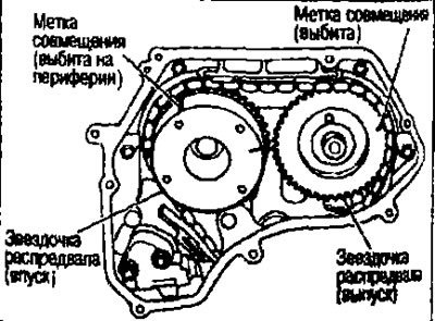
Attention:
- After alignment, the marks may shift. Therefore, after alignment, hold the timing chain with your hand.
- Before and after installing the chain tensioner, check again that the alignment marks have not shifted.
Note: Before installing the chain tensioner, it is possible to once again align the marks on the timing chain with the marks on the sprockets.
6. Install the chain tensioner
Caution: After installation, completely remove the lock pin and release the chain tensioner plunger.
7. Install the chain guide.
8. Install the intake valve timing mechanism cover as follows:
a. If removed, install the intake valve timing control solenoid valve into the cover.
b. Insert the oil scraper rings into the corresponding positions on the intake camshaft sprocket from the back of the intake valve timing mechanism cover.
c. Insert the O-ring into the front cover.
d. Apply the sealant using a syringe (suitable special tool) on the cover of the intake valve timing mechanism as shown in the figure.
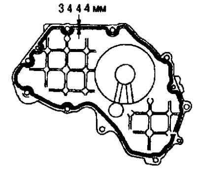
Use brand name sealant or equivalent.
Caution: Installation must be performed within 5 minutes after applying the sealant.
e. Tighten the mounting bolts in the order indicated by the numbers in the figure.
9. Install the camshaft angle sensor bracket.
a. Apply the sealant using a syringe (suitable special tool) on the camshaft angle sensor bracket as shown in the figure.
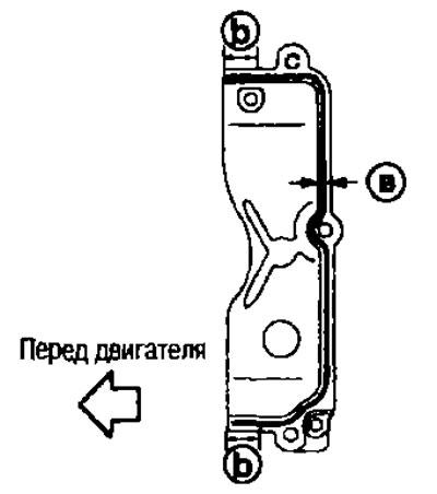
a. 2.0-3 0 mm
b. 10.5 mm
Use branded sealant or equivalent
Attention:
- After installation, remove the protruding sealant in section "b"
- Installation should be carried out within 5 minutes after applying the sealant.
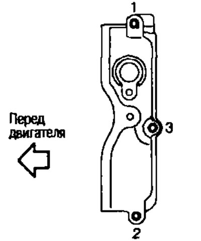
b. Tighten the mounting bolts in the order indicated by the numbers in the figure.
10. Install the camshaft angle sensor (PHASE).
11. Check and adjust valve clearances. See above.
12. After this operation, installation is performed in the reverse order of removal.
Check after removal
Camshaft runout
1. Install the camshaft on two prisms with journals No.2 and No.5.
Attention. Do not install the camshaft on the neck #1 (from the camshaft sprocket side), because its diameter differs from the other four.
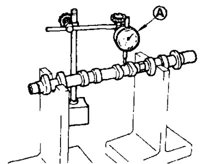
2. Fix the sensitive indicator head (A) vertically on washer No.3.
3. Turn the camshaft manually in one direction and measure the runout with a dial indicator (maximum indicator reading).
Standard: See below distribution "Technical data and specifications".
4. If the runout is different from the norm, replace the camshaft.
Camshaft lobe height
- Measure the camshaft lobe height with a micrometer (A)
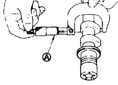
Standard and Limit: See below section "Technical data and specifications"
- If wear exceeds the limit, replace the camshaft.
Oil clearance in camshaft journals
Camshaft journal outer diameter
- Measure the outside diameter of the camshaft journal with a micrometer (A)
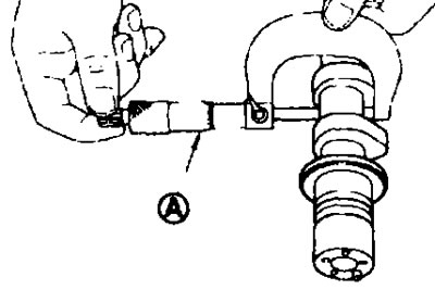
Standard. See below section "Technical data and specifications".
Inner diameter of camshaft bracket
- Tighten the camshaft bracket bolts to the specified torque. See above.
- Measure the inside diameter of the camshaft bracket with a bore gauge (A).
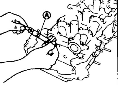
Standard: See below section "Technical data and specifications".
Oil clearance in camshaft journals
(Oil clearance in journals) = (camshaft bracket inner diameter) - (camshaft journal outer diameter)
Standard: See below section "Technical data and specifications".
- If the clearance is not within specification, replace either the camshaft or the cylinder head, or both.
Note: The camshaft bracket is integral with the cylinder head. Replace the cylinder head as an assembly.
Camshaft axial play
1. Install the camshaft into the cylinder head. See above.
2. Set the indicator (A) axially with the sensitive head against the front end of the camshaft. Measure the axial play by moving the camshaft forward/backward (in the axial direction).
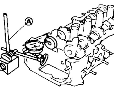
Standard: See below section "Technical data and specifications".
- If the axial play is not normal, measure the dimensions of the following components:
- Dimension "A" of journal No.1 of the camshaft.
Standard: 25.600-25.646 mm
- Dimension "B" of support bearing No.1 of the cylinder head.
Standard: 25.660-25.665 mm.
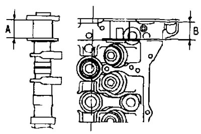
- Compare the measurement results with the standard values specified above and replace the camshaft and/or cylinder head.
Camshaft Sprocket Runout
1. Install the camshaft on two prisms with journals No.2 and No.5.
Caution: Do not install the camshaft on the prisms with journal No.1 (from the camshaft sprocket side), because its diameter differs from the other four.
2. Measure the camshaft sprocket runout with a dial indicator (maximum indicator reading).
Limit: See below section "Technical data and specifications".
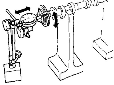
- If the runout exceeds the limit, replace the camshaft sprocket.
Valve tappet
- Check the valve lifter surface for wear or chipping.
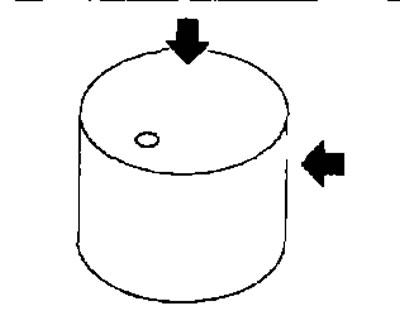
- If any defects are found, replace the valve lifter. See the section below "Technical data and specifications".
Valve tappet clearance
Valve tappet outer diameter
- Measure the outside diameter of the valve tappet with a micrometer (A)
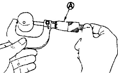
Standard: See below section "Technical data and specifications".
Valve tappet bore diameter
- Measure the diameter of the valve tappet hole in the cylinder head using a bore gauge (A).
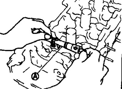
Standard. See below section "Technical data and specifications".
Valve tappet clearance
(Valve tappet clearance) = (valve tappet hole diameter) - (valve tappet outer diameter).
Standard: See below section "Technical data and specifications".
- If the obtained value is different from the standard for both the inside and outside diameters, replace either the valve lifter or the cylinder head, or both.