


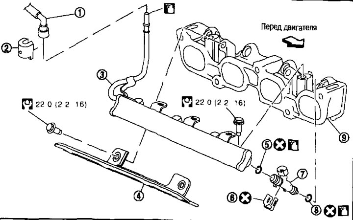
1. Fuel hose; 2. Quick release nipple cap; 3.Fuel pipe; 4. Fuel pipe protective cover; 5. O-ring (blue); 6. Clamp; 7. Fuel injector; 8. O-ring seal (brown); 9. Intake manifold support.
Caution: Do not remove or disassemble components unless instructed to do so in the illustration.
Removal and installation
Removal
Attention:
- When carrying out work in the service station premises, hang up a sign saying "FIRE HAZARD".
- Carry out work in a well-ventilated area. Have a CO₂ fire extinguisher at hand.
- Do not smoke when servicing the fuel system. Do not light a flame or create sparks.
1. Relieve the fuel pressure. See chapter "Engine management system".
2. Remove the air cleaner housing, mass air flow sensor and air duct assembly. See above.
3. Disconnect the quick release fitting (A) as follows:
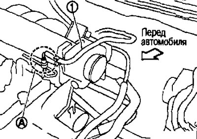
1. Fuel hose.
Caution: Disconnect the quick release fitting using a puller (special tool), and not by pulling out the locking tabs.
a. Remove the cap from the quick release fitting.
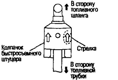
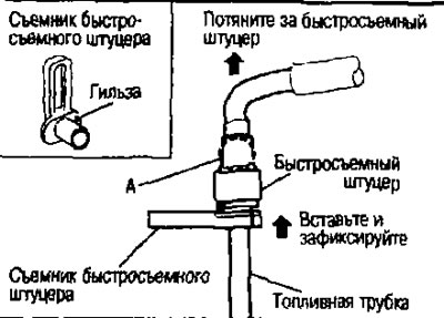
b. Put on the puller (special tool) onto the fuel pipe with the sleeve towards the quick-release fitting.
c. Insert the puller into the quick-release fitting until the sleeve rests against it. Fix the puller in this position.
Caution. The quick-release fitting will not come off if you force the puller into the fitting. Secure the puller in a position where it rests against the fitting.
d. Pull straight and remove the quick release fitting from the fuel pipe.
Attention:
- Pull the quick release fitting while holding section "A" as shown in the figure.
- Do not pull sideways. This may damage the O-ring inside the quick release fitting.
- Since fuel will spill, stock up on a container and a rag in advance.
- Do not light a fire or create sparks.
- Keep components away from heat sources. Be especially careful when welding.
- Do not expose components to battery electrolyte or other acids.
- When removing/installing, do not bend or twist the section between the quick release fitting and the fuel hose.
- To keep the connection area clean and to prevent damage and foreign particles from entering, plug the openings of the disconnected tubes with plugs or cover them with plastic bags.
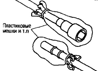
4. Remove the intake manifold. See above.
5. Disconnect the intermediate wiring from the fuel injectors.
6. Remove the fuel injectors and fuel pipe assembly.
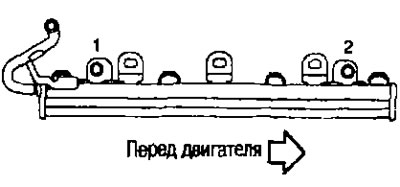
- Loosen the mounting bolts in the reverse order to that shown in the illustration.
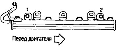
Attention:
- Make sure the fuel injector nozzle does not come into contact with other components.
- Collect any remaining fuel that has spilled from the tube with a napkin.
7. Remove the fuel injectors from the fuel line as follows:
- a. Release the clamp (1) and remove it.
- b. Remove the fuel injector (2) from the fuel pipe (3) at a right angle.
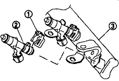
Attention:
- Do not spill any remaining fuel from the fuel pipe.
- Be careful not to damage the fuel injector nozzle when removing.
- Do not drop or hit fuel injectors.
- Do not disassemble fuel injectors.
Installation
1. When installing new O-rings into the fuel injector, observe the following:
Attention:
- The upper and lower O-rings are different. Do not confuse them.
- From the fuel pipe side, blue
- From the nozzle side, brown
- Handle O-rings with bare hands. Do not wear gloves.
- Lubricate the O-rings with engine oil.
- Do not clean O-rings with solvent.
- Make sure there are no foreign particles on the O-ring or sealing surface.
- When installing, do not scratch the seals with a tool or fingernails. Also, do not twist or stretch the O-rings. If the O-ring is stretched during installation, do not insert it into the fuel pipe immediately.
- Insert the O-ring into the fuel pipe at a right angle. Do not move or twist it.
2. Insert the fuel injectors into the fuel pipe as follows:
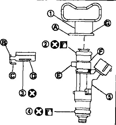
3. O-ring (blue).
4. O-ring seal (brown).
a. Insert the clamp (3) into the groove (F) on the fuel injector (5).
Insert the clamp so that the protrusion (E) on the fuel injector aligns with the notch (C) on the clamp.
Attention:
- Do not reuse clamps. Replace them with new ones.
- Position the clamp so that it does not touch the O-ring. Otherwise, replace the O-ring.
b. Insert the fuel injector into the fuel pipe with the clamp secured.
- Insert it while maintaining centering.
- Insert the fuel injector so that the protrusion (A) of the fuel pipe (1) fits into the notch (B) on the clamp.
- Make sure the fuel pipe flange (G) is securely seated in the mounting groove (D) on the clamp.
c. Check the correct installation by making sure the fuel injector does not turn or come off.
3. Install the fuel pipe and fuel injectors as an assembly as follows:
a. Insert the fuel injector tips into the intake manifold support.
b. Tighten the mounting bolts in the order indicated by the numbers in the figure.
4. Connect the intermediate wiring to the fuel injectors.
5. Install the intake manifold. See above.
6. When connecting the quick-release fittings and the fuel hose, observe the following:
a. Make sure there is no damage or foreign material build-up inside and around the fuel line and quick release fitting.
b. Align the centers and insert the quick release fitting into the fuel pipe at a right angle.
Note: The illustration shows the connection from the engine side as an example.
- Insert the quick release fitting into the fuel line until the first flange on the fuel line is fully seated in the quick release fitting and the second flange is under the bottom edge of the quick release fitting.
Caution: When inserting the fuel pipe into the quick-release fitting, hold it by section "A" as shown in the figure.
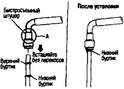
- To avoid damaging the O-ring inside the quick release fitting due to crooked installation, align the centers precisely.
- Insert until you hear a click and feel actual engagement.
- To avoid confusing engagement with a similar sound, perform the following operation:
c. Before securing the fuel line with the clamp, pull the quick release fitting, holding it by section "A". Make sure it is fully engaged (connected) so that it does not slip off the fuel line
d. Install the cap onto the quick release fitting.
- Install the cap onto the quick release fitting with the arrow pointing up.
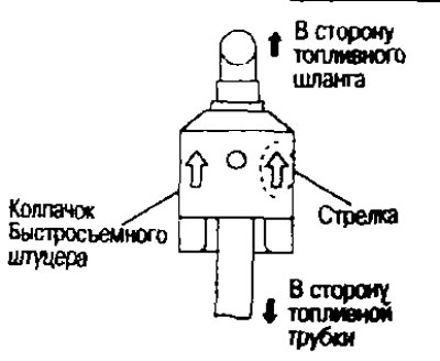
Attention:
- Make sure the quick release fitting and fuel line are securely engaged with the mounting groove on the quick release fitting cap.
- If the cap is difficult to install on the quick release fitting, the quick release fitting may not be installed correctly and check again for proper connection.
7. Secure the fuel hose with a clamp.
8. After this operation, installation is carried out in the reverse order of removal.
Post-installation check
Checking for fuel leaks
1. Turn the ignition key to the ON position (without starting the engine). After creating pressure in the fuel lines, check for fuel leaks at the joints.
Note: Use mirrors to check in hard to reach places.
2. Start the engine. Increase the engine speed and check again for fuel leaks at the fuel line junction.
Caution: Do not touch the engine immediately after stopping, as it becomes very hot.