


Table of contents: Removal ↓ Installation ↓
Removal
Note: A description of the removal and installation of the air cleaner housing and replacement of the filter element is given in Section Replacing the air cleaner filter element; a description of the removal and installation of the intake manifold is given in Section Removal and installation the intake manifold.
Air intake tract components
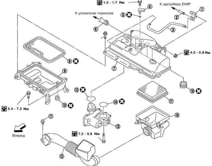
1 - EVAP Canister Purge Control Solenoid Valve; 2,3,6 - Vacuum hose; 4 - MAP sensor; 5 - Sealing ring; 7/9 - Upper/lower air cleaner housing cover; 8,10,13,14,18 - Gasket; 11 - Retainer; 12 - Air intake sleeve; 15 - Throttle actuator; 16 - Air cleaner housing; 17 - Air cleaner filter element
1. Disconnect the MAP sensor wiring connector and remove the sensor.
2. Disconnect the electrical connector and vacuum hose, then disconnect the EVAP canister purge control solenoid.
3. Remove the air intake sleeve. To do this, remove the fasteners at the front of it, turn it at an angle of approximately 90 degrees and pull it out of the air cleaner housing.
4. Remove the air cleaner housing together with the filter element (see section Replacing the air cleaner filter element) and transmission breather hose.
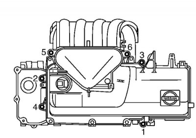
5. Remove the air cleaner covers from the intake manifold by pulling them up with uniform force. To do this, first disconnect the wiring connector from the throttle actuator, disconnect the brake booster vacuum hose, and remove the bolts in the reverse order shown in the illustration.
Note: After removal, plug any open holes in the intake manifold to prevent dirt from entering.
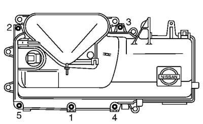
6. Remove the air cleaner cover clamp bolts in the reverse order to that shown in the illustration. Separate the covers from each other.
7. Remove the throttle actuator from the top cover of the air cleaner. Do not disassemble the actuator or apply force to it.
Installation
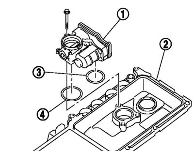
1. Install the throttle actuator (1) onto the upper cover (2) of the air cleaner. To do this, install the gasket (3) onto the flange, then the gasket (4) onto the outer groove in the throttle channel on the side of the upper cover of the air cleaner, and finally tighten the bolts securing the actuator. After disconnecting the electrical wiring of the actuator, the closed throttle position and the idle position must be programmed (see section Programming reference values for the engine management system).
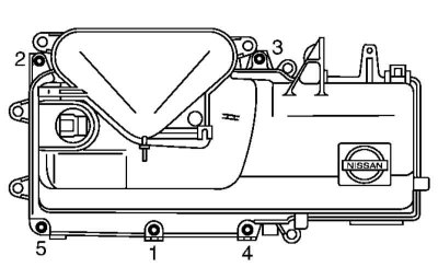
2. Tighten the air cleaner cover clamp bolts in the sequence shown in the illustration, first with force 1.9÷2.2 Nm, and then with effort 3.8÷4.4 Nm.
3. Install the air cleaner cover assembly onto the intake manifold as described in steps 4-6 below.
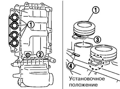
4. Install the gaskets (1) on the intake manifold and the gasket (2) on the PCV channel. The protrusion (4) on the housing must fit into the slot (3) on the gasket.
5. Place the air cleaner cover assembly onto the intake manifold while inserting the tabs at the rear into the holes in the PCV passage on the cylinder head cover.
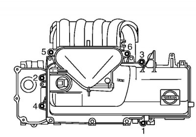
6. Tighten the air cleaner cover bolts in the sequence shown in the illustration.
7. Install the air cleaner housing with the filter element (see section Replacing the air cleaner filter element) and connect the air intake hose to it.
8. Install the EVAP canister purge control solenoid and MAP sensor. Make sure the MAP sensor O-ring and its mating surfaces are clean.