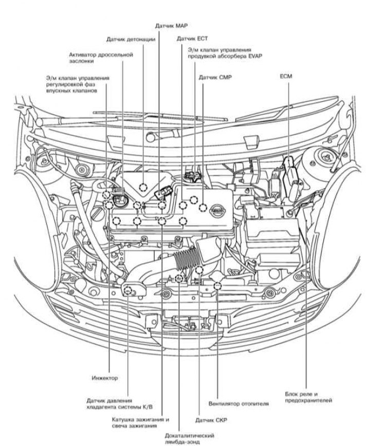
Components of the engine management system in the engine compartment
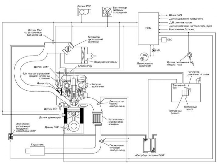
Scheme of the functioning of the engine management system
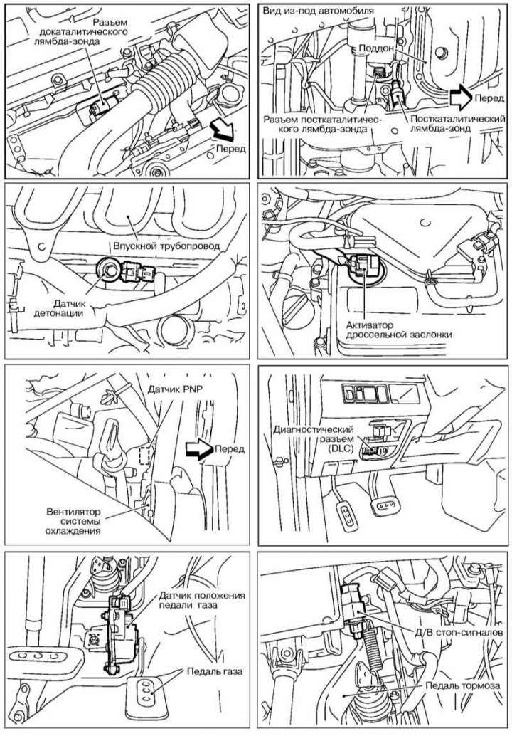
The location of the components of the engine management system, part 1
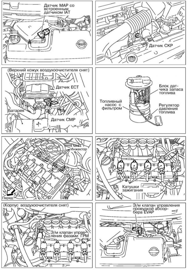
The location of the components of the engine management system, part 2
Fuel is drawn from the fuel tank by the electric fuel pump and fed through the fuel filter to the fuel distribution line. The pressure regulator maintains the pressure in the fuel system at the level 3.5 atm.
On engines through electrically controlled injectors, fuel is injected impulsively to the inlet ports, located directly in front of the engine intake valves. The engine control unit (ECM) determines the optimal ignition and injection timings, as well as the amount of fuel injected, in coordination with other vehicle systems. The high voltage for sparking on the ECM signal is generated by the ignition coils mounted above the spark plugs.
crankshaft position sensor (CKP) gives the control unit information about the number of revolutions of the crankshaft and its exact position. This information is used to determine injection and ignition timing. The CKP sensor is located on the rear side of the engine and works on the basis of the Hall effect, scanning the teeth of the rotor mounted on the crankshaft.
Camshaft position sensor (CMP) located at the rear of the cylinder head and works similarly to the CKP sensor, scanning the geared rotor at the end of the intake camshaft. The CMP sensor together with the CKP sensor is used to determine the TDC of the piston of the first cylinder, dynamically adjust the timing of the timing (via solenoid valve and inlet valve timing controller), selective control of detonation in the cylinders and for determining the injection sequence.
The air necessary for the formation of the working mixture is sucked in by the engine through the air filter and enters through the throttle valve and intake pipe to the intake valves. The amount of air intake is regulated by a throttle valve with e / drive, controlled by signals from the gas pedal position sensor. Thanks to electronic control, the air mass flow in the intake manifold can be set regardless of the position of the gas pedal, and at idle the throttle valve opens to the angle necessary to set the desired crankshaft speed. The intake air volume is determined by the intake manifold pressure sensor (MAP) with integrated intake air temperature sensor (IAT).
Knock sensor (KS) screwed into the cylinder block from the side and prevents the occurrence of impact combustion of the fuel. As a result, the ignition timing is kept at the detonation limit, which ensures a better use of the energy of the fuel and thus a reduction in fuel consumption.
Information from other sensors and control voltages supplied to the executive bodies ensure optimal engine operation in any situation. If some sensors fail, the control unit switches to the emergency program mode in order to exclude possible damage to the engine and ensure the further movement of the car. In emergency mode, the injectors fire simultaneously, 2 times per operating cycle.
The fuel tank ventilation system consists of a gasoline vapor absorber and an e / m valve. The absorber concentrates the fuel vapors formed in the tank as a result of heating the fuel. During engine operation, fuel vapors are pumped from the absorber and participate in the formation of the working mixture.
Exhaust emission reduction is carried out using a 3-function catalytic converter and lambda probes (before and after the catalytic converter).
Also, to eliminate the leakage of unburned hydrocarbons into the atmosphere, a crankcase ventilation system was used (PCV). Gases and oil vapors formed in the crankcase enter the intake manifold (due to the pressure difference - in the crankcase it is higher) and burn in the cylinders along with the fuel.
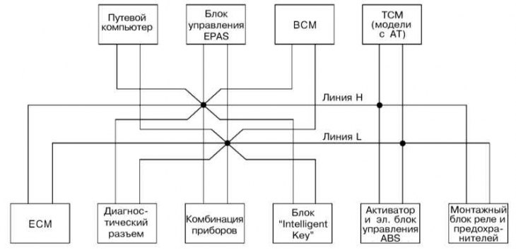
In order for multiple electronic control units to communicate with each other, these units are connected by a high-speed CAN data bus. The CAN bus consists of two lines (H and L), which reduces the amount of wiring. Each control unit can simultaneously transmit and receive data, however, each specific unit reads only the data it needs from the CAN bus.
CAN bus organization diagram