


Table of contents: Exhaust system ↓ Emission control systems ↓ Evaporative Emissions (EVAP) System ↓ Catalytic converter and lambda probes ↓
Exhaust system
The exhaust system consists of an exhaust manifold, a downpipe, a catalytic converter, mufflers and an exhaust pipe.
Emission control systems
The principle of operation of the engine management system is designed to obtain maximum output from the engine with minimum fuel consumption and toxic components in the exhaust gases. The vehicles in question are equipped with a fuel vapor recovery system (EVAP) and a crankcase ventilation system (PCV).
Note. Controlled Crankcase Ventilation System (PCV)
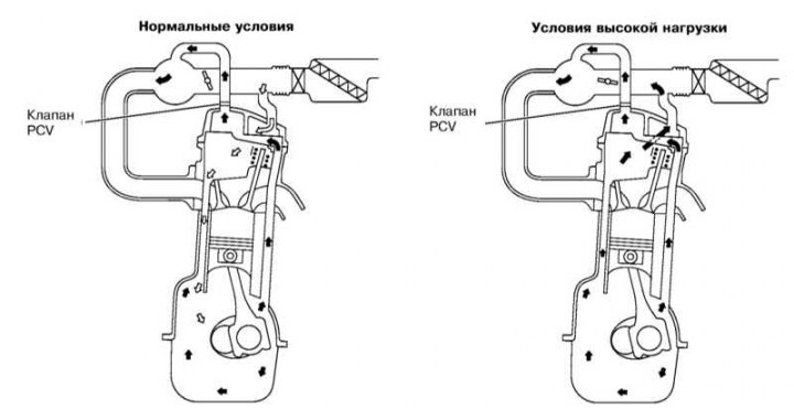
To eliminate leaks of unburned hydrocarbons into the atmosphere, the engine is completely sealed. Gases and oil vapors formed in the crankcase are fed into the intake manifold and burn in the cylinders together with the fuel.
Gases are removed from the crankcase due to the pressure difference in the crankcase and the intake manifold (crankcase pressure is higher).
PCV system operation diagram
Evaporative Emissions (EVAP) System
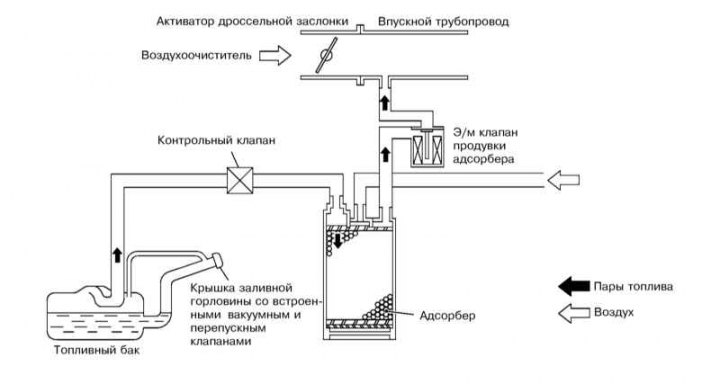
The EVAP system is designed to reduce the emission of unburned hydrocarbons into the atmosphere. The filler neck of the fuel tank is hermetically sealed with a cap. The carbon absorber collects fuel vapors that form in the tank when the car is parked and holds them there until the control unit signals the absorber to purge. During the purge, the fuel vapors are fed through the purge valve into the intake manifold, where they mix with the working mixture and then burn in the usual way in the combustion chambers.
To ensure normal engine operation at idle and during warm-up, the control unit keeps the valve closed. This prevents unburned fuel from entering the catalytic converter (at high idle speed the mixture is too rich). After the engine warms up, the valve begins to open and close, regulating the supply of fuel vapors to the intake tract.
EVAP system operation diagram
Read more on the website: NissanBook
Catalytic converter and lambda probes
To reduce the amount of harmful emissions into the atmosphere, a three-functional catalytic converter is built into the exhaust system. The fuel injection control system has a feedback loop, which includes lambda probes that constantly inform the control unit about the composition of the exhaust gas. Depending on the data received, the control unit adjusts the quality of the mixture supplied to the combustion chambers and, thus, optimizes the fuel combustion conditions.
The working surface of the lambda probes is sensitive to changes in the oxygen content in the exhaust gas. Depending on its concentration, the output voltage of the sensor changes. If the mixture is over-enriched (the oxygen content in the exhaust gas is very low), the lambda probe sends signals with low voltage. The voltage increases as the mixture becomes leaner and the oxygen content in the gases increases. The converter works most effectively with an optimal composition of the combustible mixture (14.7 parts air to 1 part fuel).