Injector and fuel rail installation components
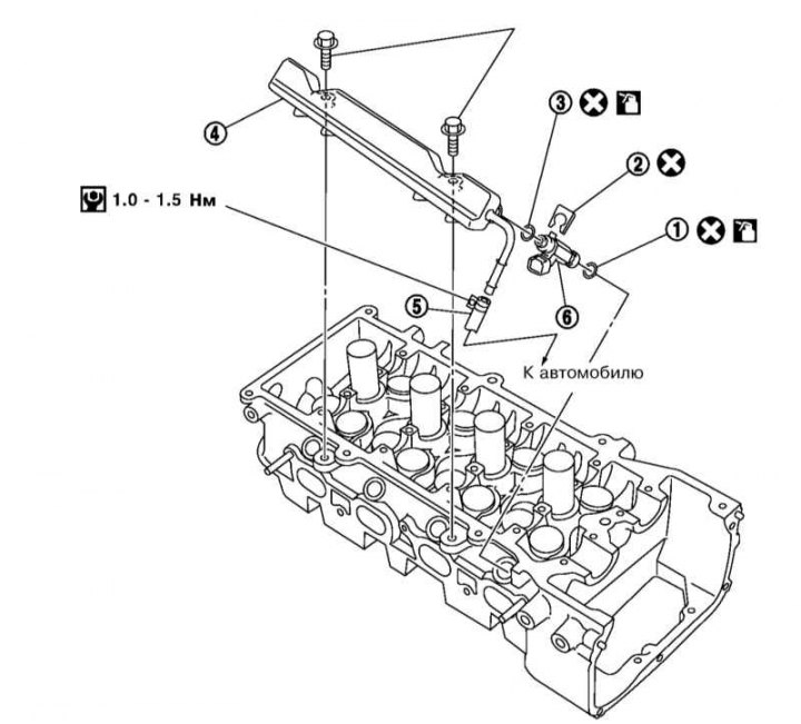
1 - O-ring (brown); 2 - Injector lock; 3 - O-ring (black); 4 - Fuel distribution line; 5 - Fuel supply pipe; 6 - Injector
1. Relieve the pressure in the supply system (see Section Depressurizing the supply system).
2. Remove the air intake sleeve and air cleaner cover assembly (see Section Removal and installation of components of an inlet air path).
3. Remove the intake manifold support bracket (see Section Removal and installation of the inlet pipeline).
4. Disconnect the fuel hose from the fuel distribution line and plug it to prevent fuel leakage.
5. Disconnect the electrical wiring of the injectors and take it aside. If disconnecting the connectors is difficult, this can be done after removing the fuel rail assembly and injectors from the cylinder head.
6. Turn out bolts of fastening of the fuel distributive highway (first - a bolt located closer to the rear of the engine) and remove the camshaft and injector assembly from the cylinder head.
Note. Do not allow injector nozzles to touch other parts.
7. Remove the injectors from the distribution line by first pulling out the injector retainer.
Note. Remove the injectors without tilting, do not damage the atomizers. Do not drop injectors, disassemble or adjust.
8. When installing injector o-rings, remember the following things:
- The upper and lower O-rings are different, install them according to the color coding: brown - on the side of the distribution line, and black - on the side of the cylinder;
- Install O-rings with bare hands, do not wear gloves;
- Lubricate O-rings with engine oil before installation;
- Do not clean O-rings with solvents;
- O-rings and mating surfaces must be free of foreign material;
- Do not scratch the O-rings with tools or fingernails, and do not twist or stretch the O-rings.
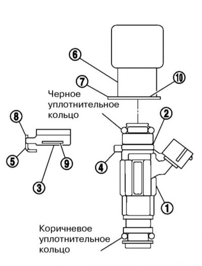
9. Install new retainer (3) into the corresponding groove (2) on the injector (1). brace (5) latch should go to the ledge (4) on the injector. Make sure the retainer does not touch the O-ring. Otherwise, replace the O-ring.
10. Install the injector (1) straight into the distribution line (6). cutout (8) on the latch should go into the ledge (7) on the distribution line, and the flange (10) should sit securely in the groove (9) latch.
11. Make sure that the injector does not rotate and does not leave the distributive highway. Repeat the procedure from step 9 for the rest of the injectors.
12. Install the assembly of the injectors and the fuel distribution line on the cylinder head, avoiding contact of the atomizers with other parts, and tighten the assembly fastening bolts first with force 11.8÷13.8 Nm, and then with force 20.8÷28.2 Nm.
Note. Tighten the bolt closest to the front of the engine first.
13. Connect a fuel hose to a distributive highway and reliably tighten its collar.
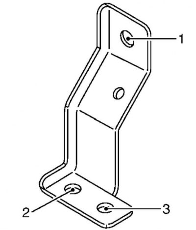
14. Establish a basic arm of the inlet pipeline and tighten its fixing bolts in the sequence specified in an illustration, at first by hand, and then with force 6.9÷9.5 Nm (bolt #1) or 8.4÷10.8 Nm (bolts #2 and #3).
15. Further installation is carried out in the reverse order of the dismantling of the components.
16. After installation, turn on the ignition (without starting the engine) after pressurizing the fuel system, check that there are no fuel leaks. Then start the engine and check the fuel lines again for leaks.