The location of the components of the power supply system in the engine compartment of the 1993 and 1994 models. issue
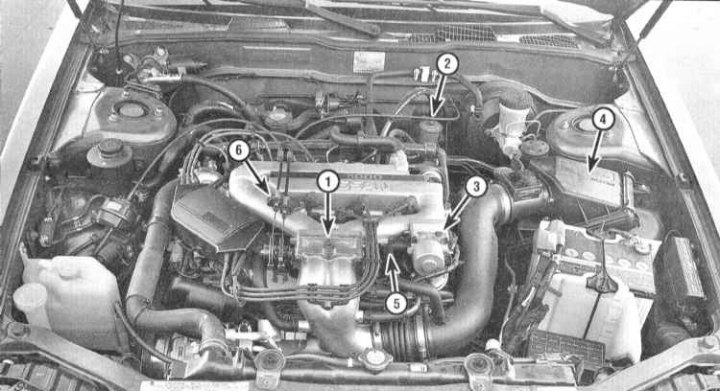
1 - Throttle body; 2 - Fuel filter; 3 - IAC valve; 4 - Air cleaner casing; 5 - Fuel line with injection injectors (under the top section of the intake manifold); 6 - Gas cable
The location of the components of the power system in the engine compartment of the V6 models
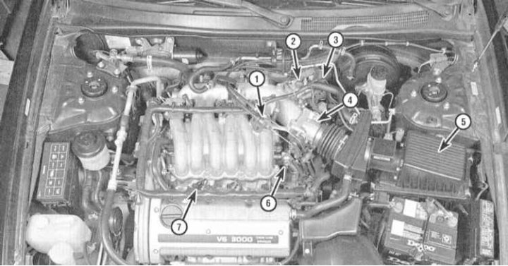
1 - Gas cable; 2 - IAC valve; 3 - Fuel filter; 4 - Throttle body; 5 - Air cleaner casing; 6 - Fuel pressure regulator; 7 - injection injector
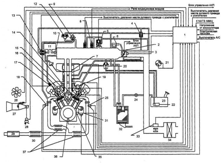
Functional diagram of the fuel injection system of 1993 and 1994 models. ed., equipped with a catalytic converter
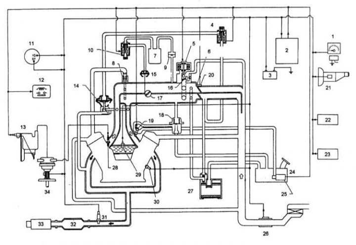
1 - VSS; 2 - ECCS control unit; 3 - Battery; 4 - EGR control solenoid valve; 5 - IAC valve; 6 - Throttle body; 7 - Equalization tank; 8 - PCV valve; 9 - One-way valve; 10 - Economizer solenoid valve; 11 - Ignition switch; 12 - Relay of fans of the cooling system; 13 - Ignition coil with power transistor; 14 - EGR valve; 15 - Economizer actuator; 16 - Air shut-off valve; 17 - Economizer; 18 - Fuel pressure regulator; 19 - injection injector; 20 - Throttle position sensor / idle switch; 21 - Start enable switch; 22 - A/C operation control switch; 23 - Power steering hydraulic fluid pressure sensor (models with AT); 24 - Fuel tank; 25 - Fuel pump; 26 - Air flow meter; 27 - Coal adsorber; 28 - Spark plug; 29 - Engine temperature sensor; 30 - Knock sensor; 31 - Oxygen sensor; 32 - Catalytic converter; 33 - Silencer; 34 - Crankshaft position sensor
Functional diagram of the fuel injection system of 1993 and 1994 models. issue without catalytic converter
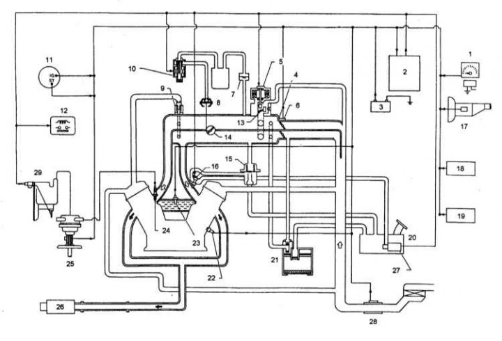
1 - VSS; 2 - ECCS control unit; 3 - Battery; 4 - Throttle body; 5 - IAC valve; 6 - Throttle position sensor / idle switch; 7 - One-way valve; 8 - Economizer actuator; 9 - PCV valve; 10 - Economizer solenoid valve; 11 - Ignition switch; 12 - Relay of fans of the cooling system; 13 - Air cut-off valve; 14 - Economizer; 15 - Fuel pressure regulator; 16 - injection injector; 17 - Sensor-switch for launch permission; 18 - A/C operation control switch; 19 - Power steering hydraulic fluid pressure sensor (models with AT); 20 - Fuel tank; 21 - Coal adsorber; 22 - Knock sensor; 23 - Engine temperature sensor; 24 - Spark plug; 25 - Crankshaft position sensor; 26 - Silencer; 27 - Fuel pump; 28 - Air flow meter; 29 - Ignition coil with power transistor
Functional diagram of the fuel injection system of models since 1995, equipped with a 3-function catalytic converter
1 - Control module; 2 - Throttle position switch; 3 - Throttle position sensor; 4 - EGR valve; 5 - IAC valve; 6 - Fast idle cam; 7 - Economizer; 8 - IAC valve; 9 - PCV valve; 10 - Economizer solenoid valve; 11 - Ignition switch; 12 - Relay of fans of the cooling system; 13 - Air cut-off valve; 14 - Economizer; 15 - Fuel pressure regulator; 16 - injection injector; 17 - Start enable switch
The power supply system consists of a fuel tank, an electric fuel pump placed in it, a fuel pressure regulator (next to the pump), EFI main relay, fuel pump relay (circuit opening relay), fuel line with injection injectors, air cleaner assembly and throttle body. All models described in this manual are equipped with an electronic multiport fuel injection system.
Multiport fuel injection system
In the system under consideration, to control the injection of fuel through injectors directly into the intake port of each of the combustion chambers of the engine, electrical impulses of a clearly limited duration are used. The moment and duration of the opening time of each of the injectors is controlled by the control module for the operation of the power unit (RSM). The PCM continuously monitors various operating parameters of the engine and, based on the incoming information, determines the required amount of fuel injected into each of the intake ports. The throttle body in this case serves only to control the air supply to the air supply system. Since each cylinder is equipped with its own injector, this scheme allows very precise control of the air-fuel mixture.
Fuel pump and fuel lines
The supply of fuel from the gas tank to the injection system and the return of its excess back to the gas tank is carried out through two metal lines laid under the bottom of the car. The submersible electric fuel pump is located inside the gas tank and is integrated into a single assembly with the fuel flow sensor unit. The fuel vapor return system carries out the removal of fuel vapors back to the gas tank through a separate return line.
The fuel pump relay consists of two windings (primary and secondary). The primary circuit is controlled by the PCM, the secondary circuit is powered directly from the battery through the ignition switch. With the ignition on (do not start the engine) The PCM energizes the relay for 5 seconds. When the engine is cranked, the PCM energizes the relay until the camshaft position sensor signals it (see chapter Engine management systems). If there are no reference pulses within five seconds, the fuel pump is switched off.
On 1995 California models and all 1996 and 1997 models. issue a fuel pump control module is provided. The module provides a reduction in the supply voltage of the pump, in all cases when the engine is running without load. The module is located in the luggage compartment under the left combination lamp assembly. A pull-down resistor is included in the wiring harness in close proximity to the module.
Exhaust system
The exhaust system consists of exhaust manifolds, a front pipe equipped with an oxygen sensor, a catalytic converter (to her), muffler and exhaust pipe. On models since 1995, no. There are two primary oxygen sensors, two heated catalytic converters and one secondary oxygen sensor.
Catalytic converters are the main components of the emission control system (see chapter Engine management systems Engine management systems).