


- Lower part of the intake manifold. This part is attached directly to the left and right cylinder heads.
- Upper part of the intake manifold. This part is attached to the bottom of the intake manifold.
- Intake pipe of the upper part of the intake manifold. This part is attached to the top of the intake manifold on one side, and the throttle body is attached to the other side.
Removal
- Disconnect the negative cable from the battery.
- Remove the engine cover.
- Drain the coolant.
Caution: This operation must be performed on a cold engine.
- Remove the air duct.
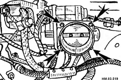
- Loosen the bolts (arrows) in a crisscross pattern, starting with any bolt, and remove the throttle body.
Caution: When operating, be careful not to hit the electric throttle actuator. The actuator cannot be disassembled.
Data posted on the website (www.NissanBook.ru)
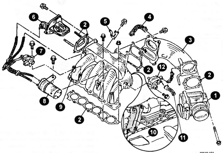
- Upper intake pipe and upper intake manifold mounting elements
1 - throttle body assembly with electric actuator; 2 - gasket; 3 - intake pipe of the upper part of the intake manifold; 4 — positive crankcase ventilation (PCV) hose; 5 — wiring harness bracket; 6 - power valve; 7 — VIAS control solenoid valve; 8 — vacuum chamber; 9 - upper part of the intake manifold; 10 — support bracket; 11 — EVAP system hose; 12 — fuel vapor tank cleaning control solenoid valve (eVAP system).
- Disconnect the vacuum hose and coolant hose from the upper intake pipe and from the upper intake manifold.
- Remove the fuel vapor canister purge control solenoid valve mounting bolt from the bottom of the intake manifold upper part of the intake manifold (eVAP system).
- Remove the VIAS control solenoid valve and vacuum chamber.
- Remove the right front wiper arm and the right front windshield panel cover.
- Disconnect the power steering hose bracket.
- Remove the intake manifold pipe support bracket.
- Remove the positive crankcase ventilation hose connecting the intake pipe at the top of the intake manifold and the right valve cover.
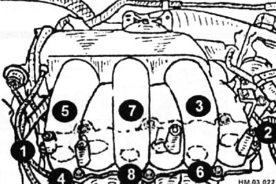
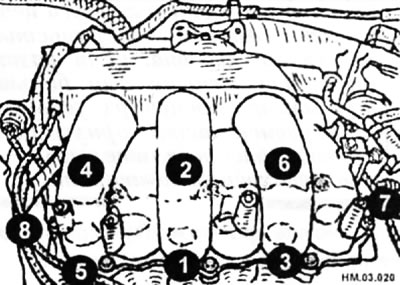
- Loosen the bolts and nuts in the sequence shown in the figure and remove the upper intake pipe and the upper intake manifold.
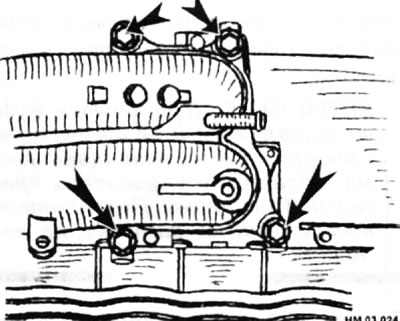
- If necessary, remove the four bolts securing the intake pipe (arrows) to the top of the intake manifold in a crisscross pattern, starting with any bolt, and separate the intake pipe from the top of the intake manifold.
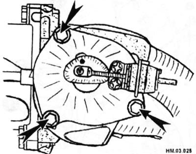
- You can also remove the power valve from the top of the intake manifold by first unscrewing the three bolts that secure it (arrows).
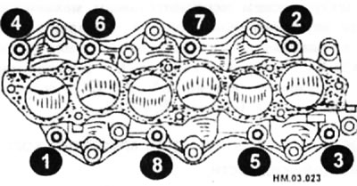
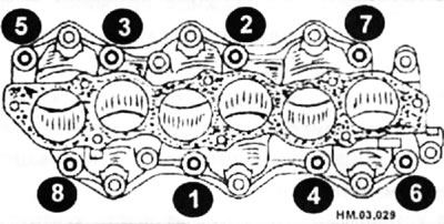
- Loosen the bolts and nuts securing the lower part of the intake manifold in the sequence shown in the figure and remove the lower part of the intake manifold.
Examination
- Wipe all mating surfaces of the removed parts with acetone or solvent.
- Using a straight edge (1) and a set of flat feeler gauges (2'), check for deformation (warping):
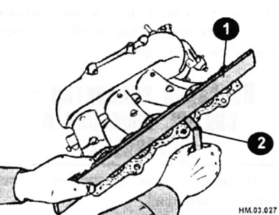
♦ mating surface of the upper part of the intake manifold with the lower part of the intake manifold;
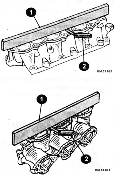
♦ mating surfaces of the lower part of the intake manifold with the upper part of the intake manifold and with the cylinder heads.
- If the deformation exceeds 0.1 mm, the warped part must be replaced with a new one.
Caution: Grinding of mating surfaces is not allowed, as is the installation of additional gaskets.
Installation
Installation is carried out in the reverse order of removal, taking into account the following:
Caution: All gaskets must be replaced with new ones, do not reuse them.
- If the studs were removed, reinstall them and tighten them to 9.8-1 1.8 N·m.
- Place the gaskets on the cylinder heads and install the lower part of the intake manifold.
- Tighten all bolts and nuts to the specified torque in two stages in the sequence shown in the figure:
♦ Stage I: 4.9-9.8 Nm;
♦ Stage II: 26.5-31.4 Nm.
- Place the upper intake manifold gasket onto the lower intake manifold.
- Install the upper part of the intake manifold pipe and tighten the mounting bolts in the sequence shown in the figure to a torque of 17.6-21.6 N·m.
- Install the power valve onto the top of the intake manifold with new gaskets and tighten the mounting bolts to 17.6 - 21.6 N·m.
- Install the upper intake manifold pipe with a new gasket and tighten the mounting bolts in a cross pattern, starting with any bolt, to 17.6-21.6 N·m.
- Install the throttle body gasket so that the three mounting tabs are neither up nor down.
- Install the throttle body onto the top of the intake manifold and tighten the mounting bolts in a crosswise pattern, starting with any bolt, to a torque of 7.2-9.6 N·m.
- Perform the throttle closed position learning procedure with the throttle actuator harness connector disconnected.
- When replacing the electric throttle control actuator, perform the air volume training procedure in idle mode and the throttle volume training procedure in closed position.