


Caution: To facilitate assembly, mark the brackets, wires and hoses to be removed before removing the cylinder head.
Removal
- Relieve fuel pressure in the fuel system.
- Disconnect the negative cable from the battery.
- Disconnect the exhaust pipe/catalytic converter from the exhaust manifold.
- Remove the air filter (if necessary).
- Disconnect the throttle cable (if necessary).
- Disconnect the wiring connectors from the throttle body, intake manifold and other parts and assemblies.
- Disconnect the vacuum hoses, coolant hoses, crankcase ventilation hoses and other hoses from the corresponding valves and pipes of the cylinder head.
- Remove the intake and exhaust manifolds.
- Remove the fuel rail with injectors assembly.
- Loosen the clamps and disconnect the hose (or hoses) cooling system from the cylinder head.
- Remove the timing chain and covers.
- Remove the camshafts.
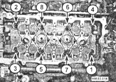
- Working in the sequence shown in the figure, loosen all cylinder head mounting bolts. Loosen the bolts in several steps, 1/2 turn at a time, until the bolts can be loosened by hand.
Sequence for unscrewing the cylinder head mounting bolts
- Remove the bolts and washers, paying attention to their position in the cylinder head.
- Remove the cylinder head. It is advisable to perform this operation with an assistant, as the head is quite heavy (especially if the manifold is not removed). Remove the gasket from the cylinder block, paying attention to the integrity of the gasket.
Note: Disassembling the cylinder head is described in detail in the relevant chapter. It's a good idea to check the cylinder head for damage, even if you're just replacing the gasket.
Cylinder head mounting elements
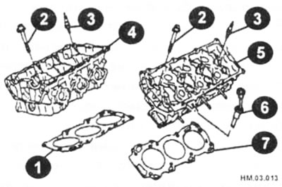
1 - right cylinder head gasket; 2 — cylinder head mounting bolt; 3 - spark plug; 4 - right cylinder head; 5 - left cylinder head; 6 — oil dipstick; 7 — left cylinder head gasket.
Preparing for assembly
- Check the condition of the threads of the cylinder head bolts, regardless of the reason for removing the head. Wash each bolt and wipe dry; if visible damage is found, replace the bolts. The manufacturer recommends checking the bolt diameter as a mandatory condition when installing the head on the engine.
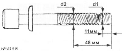
- Measure the diameters of the bolts as shown in the figure and calculate their difference (d1-d2), which should be no more than 0.11 mm.
- If the difference in any of the bolts is greater than the permissible limit, then that bolt must be replaced with a new one, however, we strongly recommend replacing all bolts every time the cylinder head is removed.
Attention: If the reduction in diameter d2 is detected not at a distance of 48 mm, but in another place, then this size is taken as the basis for d2.
- Before installing the cylinder head on the engine, thoroughly clean the mating surfaces of the head and block.
- Remove any remaining carbon deposits and gaskets with a plastic or wooden spatula, and also clean the piston bottoms from carbon deposits. When cleaning, take special care as surfaces can be easily damaged.
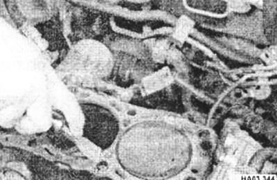
- Also, take measures to prevent the removed carbon deposits from getting into the oil channels of the cylinder block, otherwise the channels may become clogged and the lubrication of engine parts may be disrupted. Use duct tape and paper to cover the oil passages, coolant passages, and bolt holes in the cylinder block. To prevent dirt from getting into the gap between the piston and the cylinder, apply grease along the edge of the piston crown to the gap.
- After cleaning the pistons, use a brush to remove grease from the gap. Then wipe off any remaining grease with a clean cloth.
- Check for damage on the mating surfaces of the cylinder head and block (deep scratches, chips, etc.). Minor damage can be removed with a file, but serious damage can only be removed by sanding.
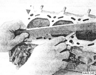
- If there is a suspicion of deformation of the mating surfaces of the head and cylinder block, then check the deviation of these surfaces from the plane using a ruler and feeler gauge.
Installation
- Wipe dry the mating surfaces of the cylinder head and block.
- Place a new gasket on the cylinder block, aligning the holes in the gasket with the pins and oil jet (if equipped).
- With the help of an assistant, carefully install the head onto the cylinder block.
- Lubricate the threads and bottoms of the bolt heads with clean engine oil.
- Place washers on the bolts so that the conical surface of the washers faces away from the bolt head.
- Carefully insert the bolts into the corresponding holes in the cylinder head. It is not permitted to install bolts under the influence of their own weight when loosened. Tighten the bolts by hand.
- Tighten the cylinder head bolts in the sequence shown in the illustration in five steps using a torque wrench.
Cylinder head bolt tightening sequence
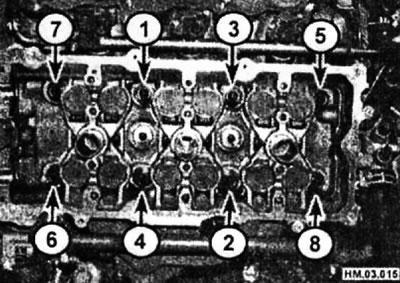
- Stage I - tighten all bolts to a torque of 98.1 Nm.
- Stage II: Wait a minute and loosen the bolts in the sequence shown in Figure HM.03.014. Loosen the bolts gradually, 1/2 turn at a time, until the bolts can be loosened by hand.
- Stage III - tighten all bolts to a torque of 34.3-44.1 N·m.
- Stage IV - tighten all bolts to an angle of 90-95°.
Note: It is advisable to tighten the bolts exactly 90°, so we recommend using an angle tightening indicator.
Angle tightening indicator
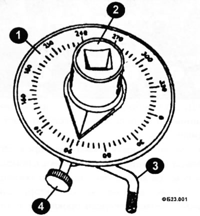
1 - graduated scale; 2 - adapter with an arrow for a square extension; 3 - adjustable stop; 4 — stop clamp wing nut.
For fasteners such as cylinder head bolts, manufacturers specify tightening torque by rotation angle rather than absolute torque. After preliminary tightening with a torque wrench, subsequent tightening stages are defined as the angles by which each bolt must be tightened. Differences in tightening torques caused by the presence or absence of dirt, oil, etc. on the threads are irrelevant. In addition, there is no need to use a torque wrench for high tightening torques.
A car enthusiast who will only use this method once or twice during the life of the car can make a cardboard template or mark the bolt heads with paint dots to indicate the correct angle. But you can do this more quickly and accurately by using one of the many industrially manufactured angle tightening indicators.
- Stage V - tighten all the bolts again to an angle of 90 - 95°.
- After installing the cylinder head, measure the head protrusion above the front of the cylinder block.
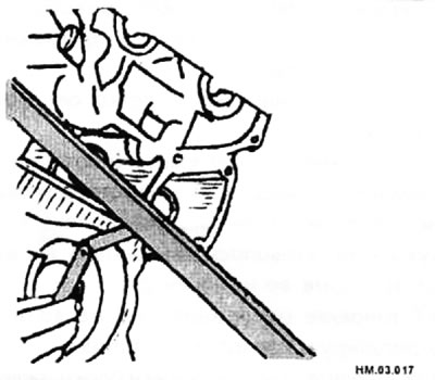
- If the cylinder head protrusion value differs from the required -14.5+0.4 mm, then the cylinder head installation must be repeated.
- Attach the coolant hose to the cylinder head and secure it securely with a clamp.
- Following the relevant chapters, perform the following operations:
- Install the camshafts.
- Install the chain and sprockets.
Caution: If the cylinder head has been overhauled, check the valve clearances on a cold engine before installing the cylinder head cover.
- Connect all wiring, hoses and control cables to the fuel system components and intake manifold.
- Connect the throttle cable.
- Attach the exhaust pipe to the exhaust manifold.
- Install the air filter and ductwork (if they were filmed).
- Start the engine and warm it up. Check the valve clearances on a warm engine.