


Removal
- Remove the engine assembly from the vehicle and separate the front suspension beam, gearbox (CVT) with the drive axle and transfer case from the engine (all-wheel drive models).
- Install engine lifting eyes.
- Place the auxiliary device on the right side of the cylinder block, then lift the engine and place it on the stand.
- Drain the engine oil.
- Remove the engine wiring harness.
- Remove the coolant hoses.
- Remove the fuel vapor canister purge control solenoid valve. Remove the drive belts and idler pulley bracket.
- Remove the power steering pump.
- Remove the generator.
- Remove the right and left valve covers.
- Remove the crankshaft position sensor (POS).
Caution: Handle the sensor with care, do not drop or hit it. Do not disassemble the sensor. Do not allow metal particles to come into contact with the magnetic part at the end of the sensor. Do not place the sensor in places where it may be affected by magnetic fields.
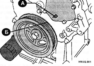
- Set the engine to TDC position (top dead center) the first cylinder in the compression stroke as follows:
♦ Turn the crankshaft pulley clockwise until the timing mark (B) (a notch in the form of an unpainted line) will not align with the pointer (A).
- Remove the upper and lower parts of the oil pan.
- Remove the front portion of the camshaft timing chain housing.
Caution: After removal, handle the housing with care and do not apply excessive force to it.
- Remove the water pump cover and chain tensioner cover from the front of the timing chain housing.
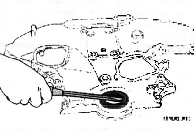
- Using a suitable tool, remove the front crankshaft oil seal from the housing.
- You can use a screwdriver to remove it.
Caution: Be careful not to damage the front of the camshaft timing chain housing.
Installation elements of camshaft drive chains
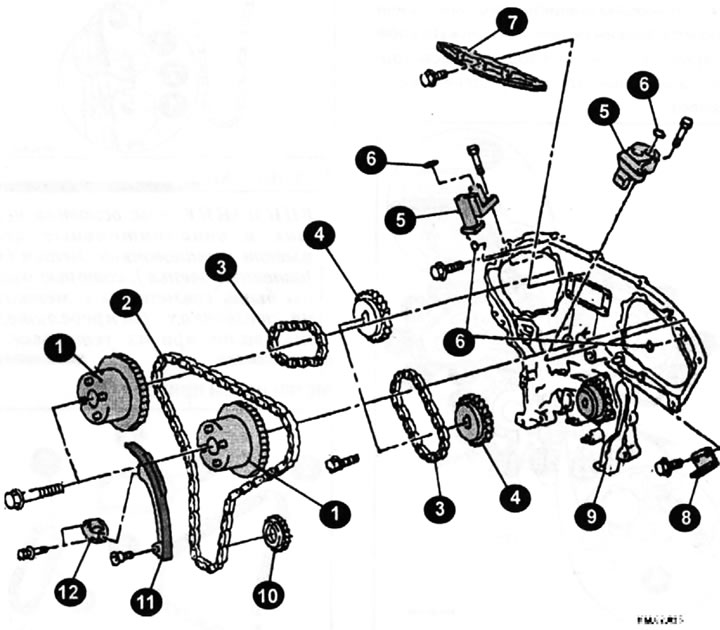
1 — intake camshaft sprocket; 2 - main camshaft drive chain; 3 - additional chain for driving the exhaust camshaft; 4 — exhaust camshaft sprocket; 5 — additional camshaft drive chain tensioner; 6 - sealing ring; 7 — chain guide; 8 - tension guide; 9 — rear part of the camshaft drive chain housing; 10 — crankshaft sprocket; 11 — chain guide; 12 — tensioner of the main camshaft drive chain.
Main chain tensioning adjustment elements
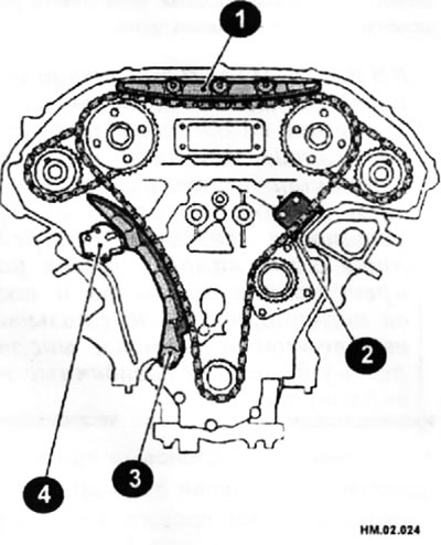
1 - chain guide; 2 - tension guide; 3 - chain guide; 4 — camshaft drive chain tensioner.
- Remove the camshaft timing chain tensioner (1) as follows: (see figure HM.02.025):
♦ Turn the lever (4) in the direction of the arrow and release the plunger locking tab (2). The plunger locking tab (2) can be pressed upwards to release.
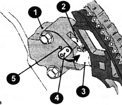
♦ To secure the lever (4), insert the locking pin (8) into the hole (5) of the tensioner housing (1) and hold the tongue (2) in the released position. For example, a 2.5 mm Allen key can be used as a locking pin.
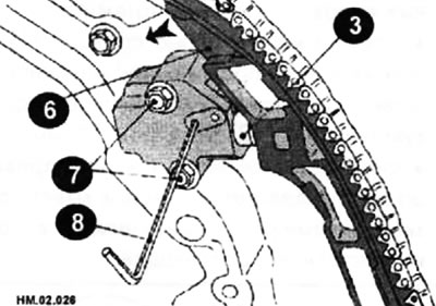
♦ Press the plunger (3) into the tensioner housing (1), pressing the chain guide (6) in the direction of the arrow.
♦ Holding the damper (6) in a pressed position, fix it with the locking pin (8) inserted through the hole in the lever (4) and the hole (5) in the tensioner housing until it stops.
♦ Loosen the mounting bolts (7) and remove the chain tensioner.
- Remove the main camshaft drive chain and crankshaft sprocket.
Attention:After removing the camshaft timing chain, do not rotate the crankshaft and camshaft separately, otherwise the valves may hit the pistons.
- Remove the cylinder head covers.
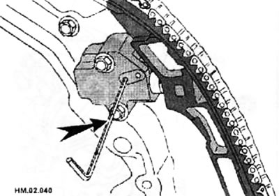
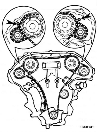
- Insert suitable locking pins (arrow) into the right and left camshaft auxiliary timing chain tensioners.
Note: Paper clips can be used as locking pins. As an example, the left row of cylinders is shown in the figure.
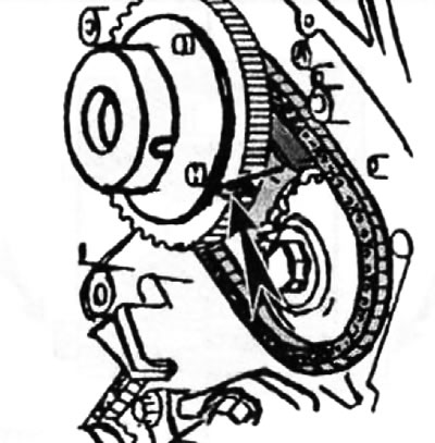
- Apply paint marks to the camshaft drive chain and camshaft sprockets for subsequent alignment during installation.
- Remove the bolts securing the camshaft sprockets for the intake and exhaust valves.
- When loosening the mounting bolts, hold the camshaft by the hexagonal section with a wrench.
- Remove the auxiliary camshaft drive chain together with the camshaft sprockets. To do this:
♦ Turn the camshaft slightly to eliminate any loose spots on the camshaft drive chain on the tensioner side;
♦ insert between the drive chain (1) and the plunger (guide) chain tensioner (2) metal or plastic plate (3) 0.5 mm thick;
♦ Remove the additional camshaft drive chain together with the camshaft sprockets from the guide groove.
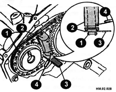
Caution: When removing the camshaft timing chain, be careful not to let the plunger fall out. This may occur because the chain tensioner plunger moves when the chain is removed and the locking pin (4) may fall out. As an example, the right row of cylinders is shown in the figure.
- The intake camshaft sprocket has a double structure and serves as a sprocket for the main and auxiliary chains.
- The intake camshaft sprocket has a complex design and should therefore be handled with extreme care, avoiding impacts or dropping.
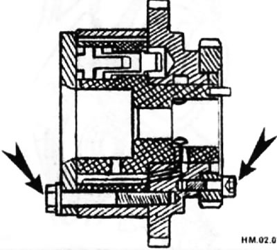
Caution: The sprocket cannot be disassembled, never loosen the bolts on the sprocket (arrows).
- Remove the chain tensioner guide.
- Remove the rear portion of the camshaft timing chain housing as follows:
♦ Loosen and remove the mounting bolts in the sequence shown in the figure.
Please note: Bolts come in different lengths. Bolts No. 1, 2, 3, 6, 7, 8, 9, 10 are 20 mm, and the rest are 16 mm. Be careful when assembling.
♦ Using a special cutter or a knife with a thin blade, cut the sealant layer and remove the rear part of the camshaft drive chain housing.
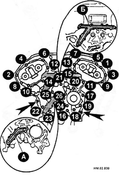
- The arrows indicate the holes for the guide pins.
Caution: Do not remove the metal plate oil gallery covers (A) and (B).
- After removing the chain housing, do not apply excessive load to it, which may cause deformation of the housing.
- If necessary, remove the auxiliary camshaft drive chain tensioners for the left and right cylinder banks from the cylinder head as follows:
♦ remove camshaft covers No. 1;
♦ Remove the additional chain tensioners together with the locking pin.
- Using a scraper, remove all traces of sealant from the front and rear of the camshaft timing chain housing and mating surfaces.
- Using a tapping tool, clean the bolt threads from sealant.
- Use a tap to clean the bolt holes of sealant.
- Using a scraper, remove all traces of sealant from the water pump cover, chain tensioner cover, and covers used to control the intake valve timing.
Examination
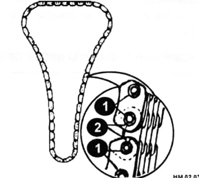
Inspect the camshaft timing chain connecting links for cracks (2) and excessive wear (1). Replace the chain if necessary.
Installation
Note: Both the main chain and the auxiliary chains have alignment marks (painted links), which must be aligned with the marks on the camshaft sprockets when they are installed.
Timing chain marks
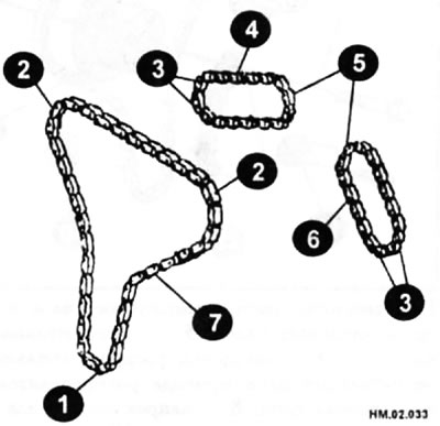
1 - orange link; 2 - yellow link; 3 - two gold links; 4 - additional chain of the right row of cylinders; 5 - the golden link; 6 - additional chain of the left row of cylinders; 7 - main chain.
Caution: When installing camshafts, tensioners, seals or other moving parts, lubricate the contact surfaces with fresh engine oil. When installing the camshaft sprockets, camshaft caps and crankshaft pulley, lubricate the bolt threads and mounting surfaces with fresh engine oil.
- If removed, install the tensioners of the additional camshaft drive chains for the right and left cylinder banks as follows:
♦ Install the additional drive chain tensioners with the locking pin inserted and a new sealing ring;
♦ Install camshaft covers No. 1.
- Install the sealing rings into the locations (A) on the cylinder block.
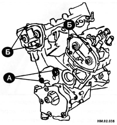
- Install the sealing rings into the locations (B) on the cylinder head.
- Apply 2.6-3.6 mm wide bead of sealant to the rear side of the rear part of the camshaft timing chain housing as shown in Figure HM.02.036.
- Align the rear of the timing chain housing and the water pump housing with the guide pins located on the left and right sides of the cylinder block and install the housings.
- Make sure that the O-rings remain in place when installing the housings onto the cylinder block and cylinder head.
- Tighten the mounting bolts in the sequence shown in the figure to the specified torque.
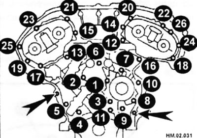
The arrows indicate the holes for the guide pins.
Please note: Bolts come in different lengths. Bolts #1, 2, 3, 6, 7, 8, 9, and 10 are 20 mm long, while all others are 16 mm long. Be careful when assembling.
- If any sealant comes out, wipe it off immediately.
- After installation, check the height difference between the rear of the camshaft timing chain housing and the oil pan surface. It should be between 0.24 and 0.1 mm. If this difference deviates from the standard value, the installation procedure must be repeated.
- Install guides for tensioning additional chains.
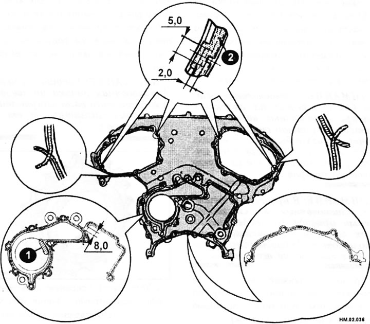
1 - sealant protrusion is not allowed in this area; 2 - groove for sealant.
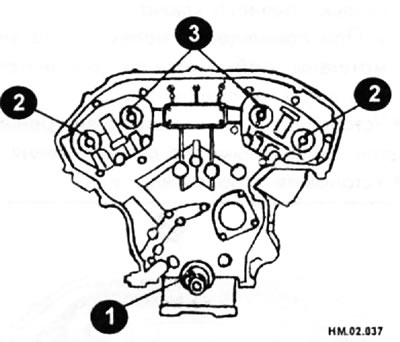
- Make sure the engine is still at TDC (top dead center) first cylinder in the compression stroke.
- Check that the guide pin hole (3), guide pin (2) and crankshaft key (1) are positioned as shown in the illustration.
Caution: The smaller diameter hole must be used for the intake camshaft guide pin. Do not confuse when identifying (ignore the larger diameter hole).
- Install the additional camshaft timing chains and camshaft sprockets as described below.
Correctly installed timing chains
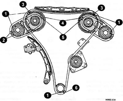
1 - timing marks on the sprockets; 2 - two gold links; 3 - yellow link; 4 - timing mark on the sprocket on the back side; 3 - the golden link; 6 - orange link.
♦ Align timing marks (2) and (5) on the additional camshaft drive chains (golden links) with stamped marks (11 and (4) on the camshaft sprockets for the intake and exhaust valves and install the sprockets.
Note: Timing marks (4) on the intake camshaft sprockets are located on the back of the sprockets and can be of two types. Round - for the right row of cylinders and oval - for the left row of cylinders.
Caution: During installation, the timing marks between the camshaft drive chain and the sprockets can easily shift. Periodically check that all marks match.
♦ Press the plungers of the additional chain tensioners and hold them in the pressed position using the locking pins (paper clips).
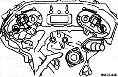
♦ Align the guide pin and pin hole on the camshaft with the notch and guide pin on the sprocket and install the sprocket.
♦ On the intake camshaft, align the pin hole on the front end of the smaller diameter shaft with the guide pin on the back of the camshaft sprocket and install the sprocket.
♦ On the exhaust camshaft, align the guide pin on the front end of the camshaft with the pin recess on the camshaft sprocket and install the sprocket.
♦ Tighten the bolts by hand to prevent the pins from moving.
♦ During and after installation, visual verification of the displacement of the installation marks may be difficult. To make checking easier, mark the top side of the sprocket teeth with paint.
- After confirming the alignment of the timing marks, tighten the camshaft sprocket mounting bolts to the specified torque.
Caution: When tightening the mounting bolt, hold the camshaft by the hexagonal section.
- Remove the locking pins from the auxiliary drive chain tensioners.
- Install the main camshaft timing chain as follows:
♦ Install the crankshaft sprocket.
Caution: Make sure that the timing mark on the crankshaft sprocket points away from the cylinder block, not towards it (arrow).
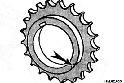
♦ Install the main camshaft drive chain as follows. so that the stamped timing marks on the camshaft sprockets are aligned with the yellow links on the chain, and the stamped timing mark on the crankshaft sprocket is aligned with the orange link on the chain.
♦ If it is difficult to align the timing marks on the main camshaft drive chain with each sprocket, slowly turn the camshaft by the hexagonal portion with a wrench to align the marks.
♦ When aligning the marks, be careful that the marks on the additional chains do not shift.
- Install the inner chain guide and tension guide.
- Install the chain guide.
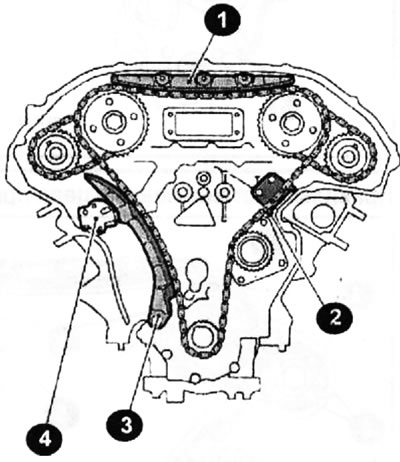
1 - chain guide; 2 - tension guide; 3 - chain guide; 4 — camshaft drive chain tensioner.
Caution: Do not overtighten the chain guide mounting bolts. If the mounting bolts are tightened correctly, there will be a gap under the bolt head. This is a normal phenomenon.
- Install the chain tensioner that presses the guide. When installing the chain tensioner, press the plunger into the housing and secure it in this position with the locking pin (arrow).
- Clean all dirt and foreign particles from the rear and mounting surface of the tensioner.
- After installation, pull out the locking pin by pressing on the chain guide.
- Install new O-rings (arrows) onto the rear of the camshaft timing chain housing.
- Install the front crankshaft oil seal (1) onto the front of the camshaft timing chain housing (2). Lubricate the oil seal lips with clean engine oil.
- Install the oil seal so that the working edge of the oil seal (4) is directed towards the inside of the engine.
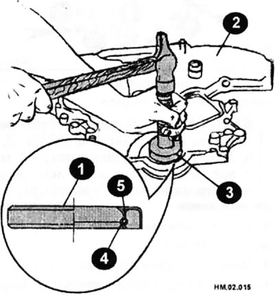
- Using a mandrel (3) or a piece of pipe of suitable diameter, drive in the seal (1) so that it is flush with the surface of the camshaft drive chain housing (2).
- Make sure that the oil seal tension spring (5) is in place and that the oil seal lip (4) is not twisted out.
- Install the water pump cover and chain tensioner cover onto the front of the timing chain housing.
- Install the front portion of the camshaft timing chain housing.
Caution: After installing the front portion of the timing chain housing, check the height difference between the front portion of the chain housing and the installation surface of the oil pan, and between the rear portion of the chain housing and the installation surface of the oil pan. If the difference is less or more than 0.14 mm, the procedure for installing the front part of the camshaft drive chain housing must be repeated.
- Install the right and left intake valve timing covers.
- Install the cylinder head covers.
- Install the crankshaft pulley.
Caution: After installing the crankshaft pulley, check that it rotates evenly in the normal direction.
- Further installation is carried out in the reverse order of removal.
Caution: After starting the engine, you may hear a dull knocking sound from the timing chain. This is normal, and the knocking should disappear once the hydraulic pressure in the chain tensioner increases.
Examination
- Before starting the engine, check the levels of coolant, engine oil and other operating fluids. If necessary, top up the operating fluid level to the normal value.
- To check for leaks, use the procedure below:
♦ Turn on the ignition (without starting the engine). Once pressure is built up in the fuel lines, check for fuel leaks at the fuel line connections.
♦ Start the engine. After increasing the engine speed, check again for fuel leaks at the fuel line connections.
- With the engine running, listen for any unusual noises or vibrations.
- Warm up the engine completely and check for coolant, engine oil, other operating fluids, fuel and exhaust leaks.
- Remove air from the lines, particularly from the cooling system lines.
- After the engine has cooled down, check the levels of coolant, engine oil and other operating fluids again. Add operating fluids if necessary.