


Table of contents: Checking drive belts ↓ Removal ↓ Installation ↓ Checking belt tension ↓ Adjusting belt tension ↓
Checking drive belts
Attention: The check is performed on a non-running, cold engine or at least 30 minutes after the engine has been stopped.
The drive belt routing diagram is provided on the drawing attached to the radiator support.
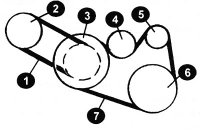
1 — power steering pump belt; 2 — power steering pump pulley; 3 — crankshaft pulley; 4 - intermediate pulley; 5 — generator pulley; 6 — air conditioning compressor pulley; 7 — alternator and air conditioning compressor belt.
With the engine off, open the hood and locate the drive belts on the front of the engine. Using a bright lamp, inspect the drive belts for separation of the rubber layers on each side of the cord (cores), cord seals, rib separation from rubber, and torn or worn ribs. Also check the belt for signs of "oxidation" which makes the drive belt appear shiny.
Cracks of the rib side (arrow) of the drive belt with V-shaped ribs (notch) are allowed in the form of small "bald spots" in the area of the ribs.
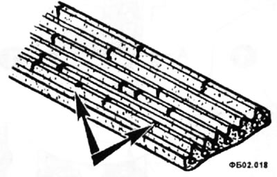
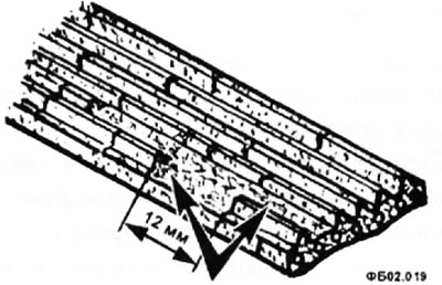
If the bald spots on the V-ribbed drive belt are greater than 11 - 12 mm on two adjacent ribs, or if the bald spots cause noise, the belt must be replaced.
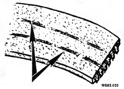
You need to check both sides of the belt, to do this you need to turn it inside out (to check the back side). The picture shows cracks running parallel to the belt ribs on the reverse side.
Feel the areas of the belt that cannot be seen with your fingers. If any of the above defects are evident, replace the belt as described below.
Removal
- Loosen the intermediate pulley lock nut (4) and use the adjusting bolt (3) to loosen the tension of the alternator and air conditioning compressor drive belt.
- Remove the belt.
- Loosen the clamp bolt (1) and the power steering pump mounting bolt (2) (the bolt is located on the rear side of the engine).
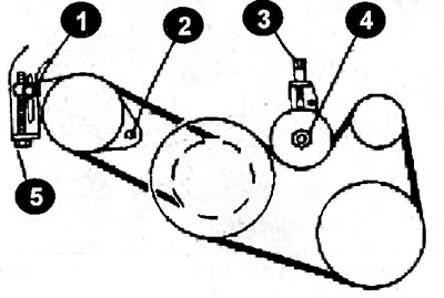
- Loosen the tension of the power steering pump drive belt with the adjusting bolt (5) and remove the belt.
Caution: If the belts are to be reinstalled, mark the top of the belts with a felt-tip pen to indicate the direction of rotation before removing them, to ensure that the belts are installed in their original position.
Installation
- Check the intermediate pulley for play; if there is play, replace the pulley.
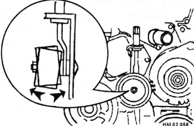
- Install the drive belts onto the pulleys in the reverse order of removal.
Caution: When installing, do not twist or bend the belt too much.
- Make sure the belt is properly aligned with the pulley grooves.
- Check for oil and coolant on drive belts and pulleys.
- Adjust the tension of the drive belts.
Caution: Grease is applied to the idler pulley adjusting bolt (3). Be careful not to let any lubricant get on the belt, as this may damage it.
Checking belt tension
Caution: When checking the drive belt deflection or tension after installing it, first adjust the tension to the required value. Then, after turning the crankshaft two or more revolutions, the adjustment must be repeated to avoid differences in belt tension between the different pulleys.
- Measure the drive belt tension using a special device at the locations (1) and (2) shown in the figure.
Caution: If the belt tension checker cannot be installed at the indicated locations, check the drive belt tension at other locations, such as locations (3) and (4).
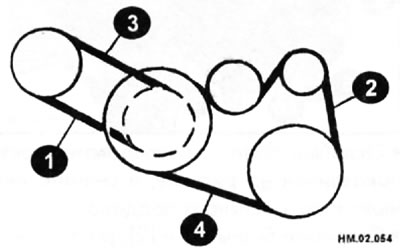
- When measuring deflection, apply a force of 98 N.
- If the belt deflection exceeds the maximum allowable value or if the belt tension deviates from the normal value, make adjustments.
Belt deflection
| Drive belt | New | Pre-owned | |
| Maximum permissible value | After adjustment | ||
| Generator and air conditioning compressor | 3,7-4,1 | 7 | 4,2-4,6 |
| Power steering pump | 6,5-7,2 | 11 | 7,3-8 |
Please note: Deflection is measured in mm with a force of 98 N applied to the belt.
Belt tensioning
| Drive belt | New | Pre-owned | |
| Maximum permissible value | After adjustment | ||
| Generator and air conditioning compressor | 838-926 H | 294 N | 730-818 N |
| Power steering pump | 603-691 H | 196 N | 495-583 N |
Adjusting belt tension
When replacing the drive belt, to improve alignment with the pulley grooves, adjust the tension of the new belt to the values specified in the "New Belt" column.
If the deflection or tension of a used belt exceeds the maximum allowable values, adjust to the values specified in the "After Adjustment" column for the used belt.
When checking the drive belt deflection or tension immediately after installation, first adjust the tension to the required value. Then, after turning the crankshaft two or more revolutions, the adjustment must be repeated to avoid differences in belt tension between the different pulleys.
When installing the belt, make sure that it fits correctly into the pulley grooves.
•Remove the right mudguard.
Loosen the idler pulley lock nut (4) and adjust the tension of the alternator and air conditioning compressor drive belt with the adjusting bolt (3).
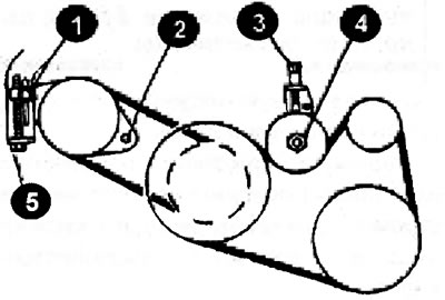
- The correct drive belt tension value is shown in the table.
- Tighten the idler pulley locknut (4) by hand and measure the belt deflection or tension without loosening.
- Tighten the lock nut (4) to a torque of 30.4-39.2 Nm.
- Tighten the adjusting bolt (3) to a torque of 3.9-6.9 Nm.
- Loosen the clamping bolt (1).
- Loosen the power steering pump mounting bolt (2) (the head of the bolt (2) is located at the rear of the engine).
- Adjust the tension of the power steering pump drive belt using the adjusting bolt (5).
- The correct drive belt tension value is shown in the table.
- Tighten the tie bolt (1) to 24.5-31.4 Nm.
- Tighten the power steering pump mounting bolt (2) to 36.3-50.0 N·m.