


Camshaft mounting elements
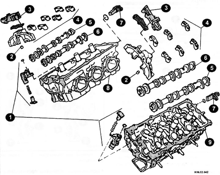
1 - additional chain tensioner; 2 - guide pin; 3 — intake valve phase control solenoid; 4 - camshaft bearing caps; 5 - camshaft for exhaust valves; 6 - camshaft for intake valves; 7 — camshaft position sensor; 8 - right cylinder head; 9 — left cylinder head.
Removal
- Remove the front camshaft timing chain housing, camshaft sprockets, camshaft timing chain, and rear camshaft timing chain housing.
- If necessary, remove the camshaft position sensors from the rear of the cylinder head.
Caution: Handle the sensors with care, do not drop or hit them, and do not place the sensors in places where they may be exposed to magnetic fields. Do not disassemble the sensors or allow metal particles to adhere to the magnetized sensor tips.
- Measure the axial clearance of the camshaft using a dial indicator, moving the camshaft back and forth along its axis.
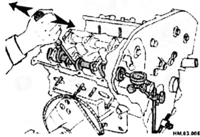
The standard value of axial clearance should be 0.1 15 - 0.1 8 8 mm, and the maximum permissible value is 0.24 mm.
- If the axial clearance exceeds the maximum permissible value, replace the camshaft and repeat the measurements.
- If in this case the axial clearance of the camshaft exceeds the maximum permissible value, the cylinder head must be replaced.
- Remove the intake valve timing control solenoids.
Caution: Intake valve timing solenoid valve gaskets must be discarded as they are not reusable.
- Remove the back cover by prying it off with a special tool.
- On vehicles, the camshaft journal bearing caps are numbered. The numbers are cast in the upper central part of the covers (arrow).
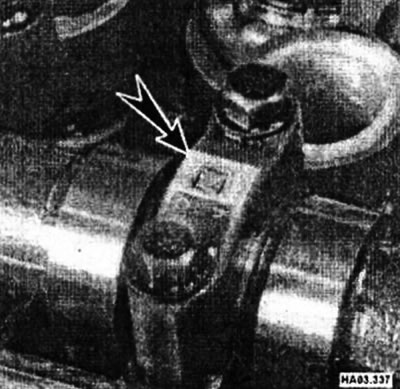
- If there are no marks, then before removing them, you need to apply the appropriate marks with white paint or a special marker. Labels must indicate the serial number and orientation of the lid. This is necessary to avoid incorrect installation of the covers during assembly.
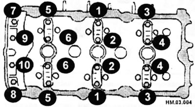
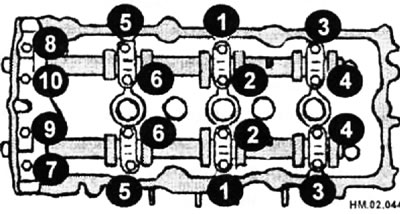
- Loosen the camshaft journal bearing cap mounting bolts, following the sequence shown in the figure. The left cylinder head is shown as an example, the right one is similar.
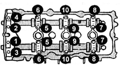
- Loosen the bolts in several stages. This is necessary to evenly and gradually weaken the forces from the valve springs acting on the covers. After the springs have completely released, the bolts can be completely unscrewed. First remove the front and rear covers, then remove the distributor caps and exhaust shaft caps. Remove the intake camshaft covers last.
- Remove the camshafts from the cylinder head.
- Prepare 24 plastic bags and number them from 1 to 24. You can also use a box with 24 compartments.
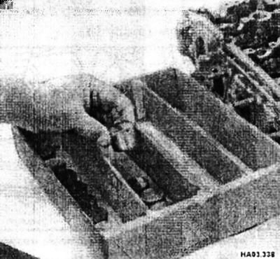
- Use a rubber suction cup to remove the pushers and place them in a bag (or department) with the corresponding number. Do not mix up the tappets, otherwise accelerated engine wear may occur
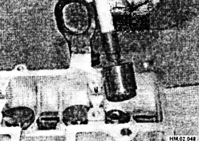
Caution: Do not use a magnet to remove the tappets, as the tappet will become magnetized and tiny shavings will stick to it during engine operation (traces of wear on parts), which in turn will cause accelerated wear of both the tappets themselves and the camshafts with valves.
Checking the status
- Inspect the surfaces that contact the camshaft journals in the covers and in the cylinder heads. Check the surfaces for burrs and traces of deep wear. Check the camshaft cams for signs of metal chipping (areas of bluish honey fungus), deep grooves, chips, flat areas formed due to wear.
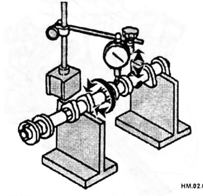
- Install the camshaft journals #2 and #1 in the prismatic bearings and use a dial indicator to check the runout in journal #3. If the runout exceeds 0.05 mm, replace the camshaft.
- Using a micrometer, measure the size of each camshaft lobe.
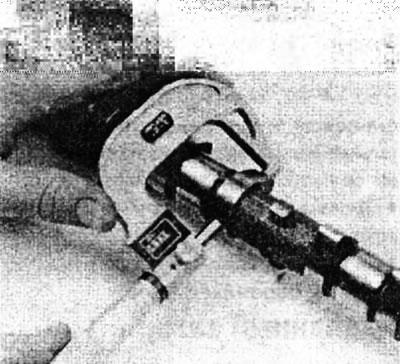
- The standard value for both intake and exhaust camshafts should be 44.96+0.095 mm. If signs of damage are detected or if excessive wear exceeds 0.2 mm, replace the camshaft. Now check the clearance in the camshaft bearing journals. This can be done in two ways - either by direct measurement or by using a plastic Plastigage gauge.
- When measuring the clearance using the direct method, install the camshaft bearing caps on the cylinder head, maintaining their previous order and orientation. Tighten the cover bolts to the specified torque in the sequence shown in the illustration. The right cylinder head is shown as an example, the left one is similar.
- Measure the inside diameter of the bearing surfaces of the covers. The standard value for neck No. 1 should be 26.01 1+0.01 mm, and for the rest -23.511 ±0.01 mm.
- Measure the diameter of the camshaft bearing journals. The standard value of the diameter of the support neck No. 1 should be 25.945±0.01 mm, and for the rest - 23.455+0.01 mm.
- The clearance in the bearing journals is defined as the difference between the internal diameter of the hole for the journal with the cover installed and the diameter of the bearing journal of the camshaft.
- The standard clearance value for neck No. 1 should be 0.065+0.02 mm, and for the rest - 0.055±0.02 mm.
- If the gap exceeds the maximum permissible value of 0.15 mm, then one or both camshafts and the cylinder head must be replaced.
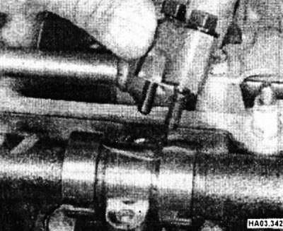
- When measuring clearance with a Plastigage, clean both camshafts, the bearing surfaces of the journals in the cylinder head and in the caps with a clean, lint-free cloth. Place the camshafts into the cylinder head.
- Place pieces of plastic calibration wire along the bearing surfaces of the camshaft journals parallel to their axis. Having taken measures to prevent the camshafts from turning, install the camshaft covers and tighten the bolts securing them to the required torque.
- Loosen the cover mounting bolts and carefully remove the covers, preventing the camshafts from turning
- Compare the largest width of the crushed wire from each neck with the scale on the gauge package.
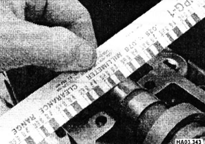
- If the gap exceeds the maximum permissible value (0.15 mm), then measure the diameter of the camshaft journal with a micrometer. If the diameter is less than the maximum permissible value, replace the camshaft and check the clearances in the bearing journals again. If the gap still exceeds the maximum permissible value (0.15 mm), replace the cylinder head.
Note: Since the inner diameter of the camshaft covers is determined during the cylinder head production process, it is necessary to replace the entire cylinder head.
- Install the camshaft with journals No. 2 and No. 4 in the prismatic supports and use a dial indicator to determine the runout of the camshaft sprocket (maximum value on the indicator scale). The maximum permissible runout value should be 0.15 mm.
- If the runout exceeds the maximum permissible value, the camshaft sprocket must be replaced.
- Check for signs of wear on the tappets and inner surfaces of the cylinder head. If the necessary measuring instruments are available, the degree of wear can be assessed by the difference in diameter between the tappet and the hole in the cylinder head. The standard tappet diameter should be 33.982±0.005 mm. The standard bore diameter should be 34.008±0.008 mm. The standard valve tappet clearance should be 0.026±0.013 mm. If the clearance exceeds the maximum permissible value, the tappet or cylinder head must be replaced.
Installation
- Generously lubricate the tappets and tappet bores in the cylinder head with engine oil. Carefully insert the pushers, without disturbing their original installation order. When installing, the pusher must be inserted into the hole without distortion. Insert adjusting washers into the tappets, making sure they are installed correctly.
- Generously lubricate the camshaft journals and camshaft lobes with engine oil.
- Install the additional camshaft drive chain tensioners.
- Install the camshafts into their places in the cylinder head.
- The intake and exhaust camshafts are not the same.
Camshafts
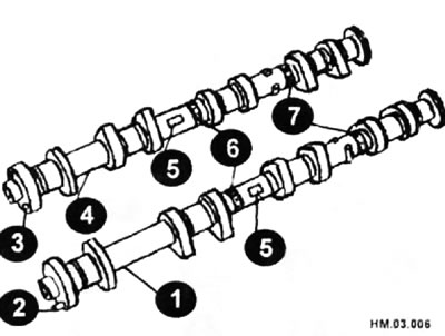
1 — exhaust camshaft; 2 - guide pin; 3 — hole for the sprocket guide pin; 4 — intake camshaft; 5 - identification mark; 6 - color mark M1; 7 - color mark M2.
| Tags and Features | Intake camshaft | Exhaust camshaft | ||
| right | left | right | left | |
| Guide pin | no | there is | ||
| Hole for guide pin | there is | no | ||
| Colored mark M1 | Pink | no | ||
| Colored label M2 | no | Orange | ||
| Identification tag | RE | LH | RE | LH |
Caution: Remember that the intake camshafts have two holes, one of which is (smaller diameter) designed for sprocket guide pin. Therefore, when installing the camshaft, it should be oriented precisely according to the smaller hole.
- Make sure that the contact surfaces of the bearing caps and cylinder head beds are absolutely clean and that there are no scratches or traces of oil on these surfaces. Apply a thin layer of sealant to the mating surfaces of the front camshaft bearing caps.
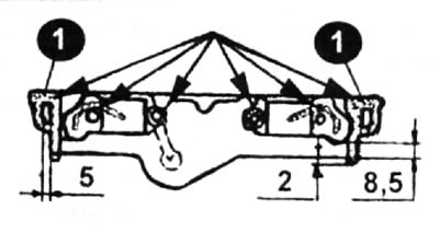
- Apply 2.0-3.0 mm wide bead of RTV silicone sealant to the mating surface of cover No. 1 of the right or left cylinder bank camshafts as shown in the figure (arrows).
Attention: After the sealant has hardened, when all the covers have been tightened to the required torque, it is necessary to remove the protruding sealant from the front side of the cover in places (1).
- Install the bearing caps, following the marks made during removal (or existing), so as not to disturb the previous order of the lids.
Note: Instead of identification marks on the camshaft bearing caps, there may be stamped marks A, B, C and L, M, P for exhaust camshafts, D, E, F and G, J, K for intake camshafts of the right and left cylinder heads, respectively.
Camshaft bearing caps
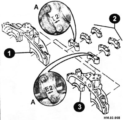
1 — cover No. 1 of the right cylinder head; 2 — covers No. 2-4; 3 — cover No. 1 of the left head (cylinder block; A — location of identification marks on covers, where I is the intake camshaft; E - exhaust camshaft; 2 - Cover No; arrow - front of engine.
- Tighten the cover mounting bolts in the sequence shown in the figure below. Tighten the bolts evenly, gradually increasing the force, turning the bolts one turn at a time, until the covers contact the cylinder head. Then tighten the bolts to the specified torque in three stages. Tighten only in the order specified to ensure a uniform and gradual increase in force from the valve springs to the camshaft.
Stage I - tighten bolts No. 7-10, and then bolts No. 1-6 to a torque of 1.96 N·m.
Stage II - tighten all bolts in order to a torque of 5.88 Nm.
Stage III - tighten all bolts to a torque of 9.02-1 1.8 N·m.
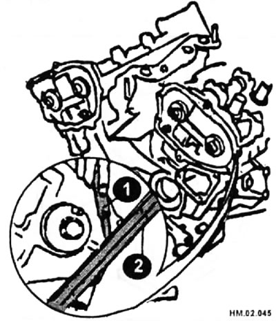
- Measure the amount of protrusion of the front side of cover No. 1 above the cylinder head using a set of feeler gauges (1) and a flat block (2).
- The protrusion value should be 0+0.14 mm, if the measured value differs from the required one, then the camshafts and camshaft covers must be reinstalled.
- Check and adjust valve clearance.
- Further installation is carried out in the reverse order of removal.
Valve clearance
Examination
- After removing, installing or replacing the crankshaft or valve train components, check the valve clearances. Checking is also necessary if loud and clear clicking sounds are heard from under the valve covers.
- Checking and adjusting the valve clearance is carried out in three stages at three different positions of the crankshaft.
Stage I - the piston of cylinder No. 1 is at TDC;
Stage II - the piston of cylinder No. 3 is at TDC;
Stage III - the piston of cylinder No. 5 is at TDC.
At each stage, only certain valves need to be adjusted, according to the table provided nearby.
- Remove the right and left valve covers.
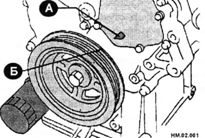
- Set the piston of cylinder No. 1 to the TDC position of the compression stroke. The installation mark (B) must be located opposite the pointer (A).
- Check that the camshaft lobes for the intake and exhaust valves of the first cylinder (front side of the right bank of engine cylinders) are located as shown in the figure (arrows).
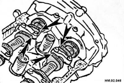
- If this is not the case, turn the crankshaft pulley one full turn clockwise (if you look from the front). Using a set of flat feeler gauges, determine the valve clearances.
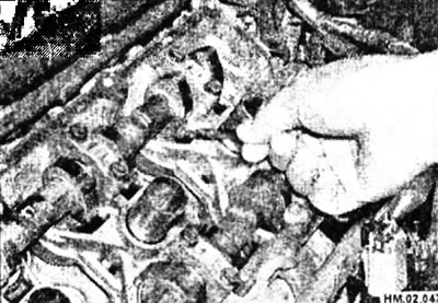
Note: Valve clearance can be checked and adjusted both on a cold and hot engine. An engine is considered cold if the coolant and engine oil temperatures are the same as the ambient air temperature, but not below +20°C. An engine is considered hot if the coolant and engine oil temperatures are not below +80°C.
| cylinder number | Piston of cylinder No. 1 at TDC | Piston of cylinder No. 3 at TDC | Piston of cylinder No. 5 at TDC | |||
| Valves to be tested | Valves to be tested | Valves to be tested | ||||
| inlet | graduation | inlet | graduation | inlet | graduation | |
| 1 | + | + | ||||
| 2 | + | + | ||||
| 3 | + | + | ||||
| 4 | + | + | ||||
| 5 | + | + | ||||
| 6 | + | + | ||||
- After checking and, if necessary, adjusting the valves with the piston of cylinder No. 1 at TDC, set the piston of cylinder No. 3 to TDC by turning the engine crankshaft 240° clockwise (if you look from the front).
- Check and, if necessary, adjust the clearances of the required valves (see table).
| Valve clearance (mm) | Engine | |
| cold | hot | |
| Intake | 0,3±0,04 | 0,36+0,056 |
| Graduation | 0,33+0,04 | 0.37±0,062 |
- After turning the crankshaft by 240°, set the piston of cylinder No. 5 to the TDC position, check and, if necessary, adjust the clearances of the required valves (see table).
Caution: The crankshaft pulley mounting bolt flange has stamped lines spaced 60° apart. Therefore, when turning the crankshaft by 240°, you can use these lines as a guide.
- If any valve clearance differs from the required value, make adjustments.
Adjustment
- Adjustment is made by selecting valve tappets of different thicknesses.
- Valve tappets are available in 27 different thicknesses: from 7.88 to 8.40 mm in 0.02 mm increments.
- The thickness of the new valve tappet can be determined by the mark located on the back of the tappet (inside the pusher cylinder). The 788U or 788R mark corresponds to a thickness of 7.88 mm.
- Remove the camshaft.
- Remove those valve lifters whose valve clearance value differs from the required one.
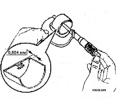
- Using a micrometer, measure the thickness of the removed valve lifter at its center, and calculate the thickness of the removed lifter using the formula below.
N=R+(M-0.30 mm) - for intake valves;
N = R+(M-0.33 mm) - for exhaust valves, where R is the thickness of the removed tappet, N is the thickness of the new tappet; M - measured valve clearance.
- Install the selected valve lifter.
- Install the camshaft.
- Manually rotate the crankshaft pulley a few revolutions.
- Check that the valve clearances on a cold engine meet the required values.
- After completing the operation, be sure to check the valve clearances again on a warm engine and make sure that they correspond to the required values.