


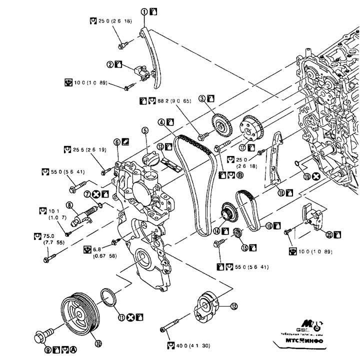
1. Chain guide at the bend; 2. Timing chain tensioner; 3. Exhaust camshaft sprocket; 4. Timing chain; 5. Oil filler cap; 6. Front cover; 7. O-ring seal; 8. Solenoid valve of the intake valve timing control mechanism; 9. Crankshaft pulley bolt; 10. Crankshaft pulley; 11. Front oil seal; 12. Automatic drive belt tensioner; 13. Timing chain tensioner guide (from the side in front of it the lid); 14. Crankshaft sprocket; 15. Balancing block sprocket; 16. Purpose of the balancing unit drive; 17. Intake camshaft sprocket; 18. Timing chain tensioner guide; 19. O-ring seal; 20. Balancer drive chain tensioner; A. See below; B. See below.
Removal and installation
Removal
Note: The direction of rotation indicated in the text refers to the rotation as viewed from the front of the engine.
1. Remove the front right wheel.
2. Remove the protective cover from the right front fender. See chapter "Interior and exterior body equipment".
3. Drain the engine oil. See chapter "Lubrication system and engine cooling system".
Caution: Perform this operation when the engine is cold
4. Remove the following components.
- intake manifold; see above;
- valve cover; see above;
- drive belt; see above.
5. Set the piston of cylinder No.1 to TDC in the compression stroke as follows:
a. Turn the crankshaft pulley (1) clockwise and align the TDC mark (colorless risk) (8) with timing indicator (A) on the front cover.
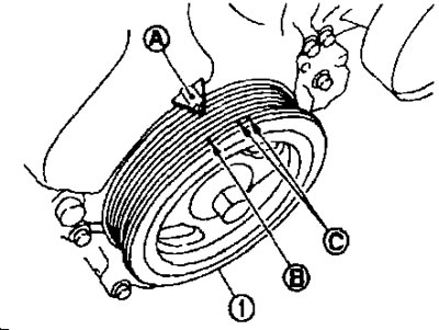
C. Mark with white paint (not used during maintenance).
b. At the same time, make sure that the working lobes of the camshafts of the intake and exhaust valves of the cylinder are facing each other (
 ) as shown in the figure.
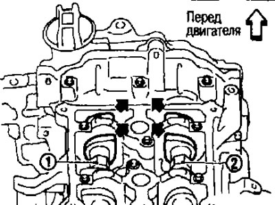
1. Intake camshaft.
2. Exhaust camshaft.
- Otherwise, rotate the crankshaft pulley one more revolution (360°) and align them as shown in the figure.
6. Remove the crankshaft pulley as follows:
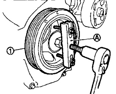
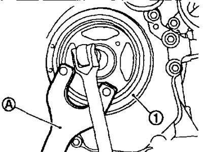
a. Secure the crankshaft pulley (1) with the holder (A) (suitable special tool), loosen the crankshaft pulley bolt so that it moves 10 mm from its original position.
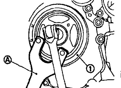
Caution: Do not remove the crankshaft pulley bolt as it will serve as a point of friction for the pulley puller (special tool: KV111030000).
b. Secure the crankshaft pulley puller (A) (special tool: KV111030000) in the M6 holes of the crankshaft pulley and remove the crankshaft pulley.
7. Remove the rear torque rod. See below.
8. Support the bottom of the engine with a telescopic strut and remove the strut and right engine mount insulator. See below.
9. Oil pan (lower). See above.
Note: If the crankshaft sprocket and balancer unit components are not removed, this step can be skipped.
10. Remove the intake valve timing control solenoid valve.
11. Remove the automatic drive belt tensioner.
12. Remove the front cover as follows:
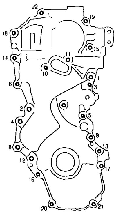
a. Loosen the mounting bolts in the reverse order to that shown in the illustration.
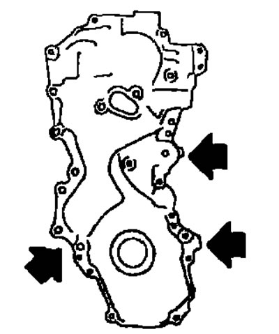
b. Pry the cover off in the places indicated by arrows (
 ) in the picture, cut off the sealant and remove the front cover.
Attention:
- Do not damage the contact surfaces.
- When shipped from the factory, a stronger sealant is applied compared to the sealants used previously. Therefore, do not attempt to separate the cover in places not intended for this purpose.
13. Remove the front oil seal from the front cover.
Attention:
- Be careful not to damage the front cover.
- Remove the front oil seal using a screwdriver.
14. Remove the chain tensioner as follows.
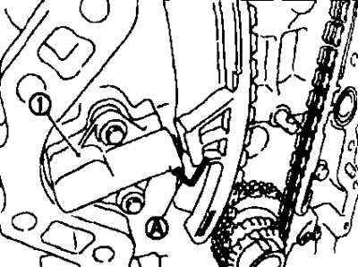
a. Press in the chain tensioner plunger.
b. Insert the lock pin (A) into the hole in the tensioner body and lock it with the plunger pressed in.
Note: A metal rod with a diameter of approximately 1.5 mm can be used as a locking pin.
c. Remove the chain tensioner. (1)
15. Remove the timing chain guide at the bend (2), the timing chain tensioner guide (3) and the timing chain (1).
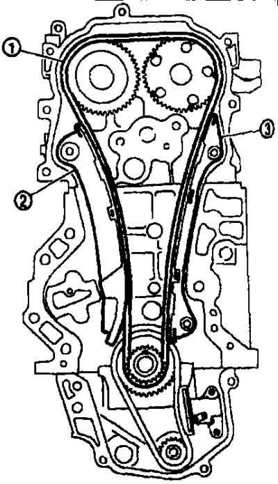
Caution: After removing the timing chain, do not turn the crankshaft or camshaft separately, otherwise the valve will hit the piston crowns.
16. Remove the crankshaft sprocket and balancer unit components as follows:
a. Raise the lever (A) fully and press the timing chain guide at the bend (B) into the timing chain tensioner (oil pump) (1).
- The guide at the bend is released when the lever is fully raised. As a result, it can be moved.
b. Insert the lock pin (D) into the hole in the tensioner housing (C) and fix the timing chain guide at the bend.
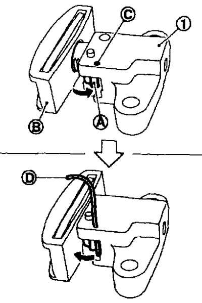
Note: A metal rod with a diameter of approximately 1-2 mm can be used as a locking pin.
c. Remove the balancer unit drive chain tensioner.
- If the hole in the lever does not align with the hole in the tensioner housing, align them by slightly moving the guide at the bend.
d. Fix the balance shaft by the hexagonal part (19.0 mm) (A) and loosen the balance block sprocket bolt.
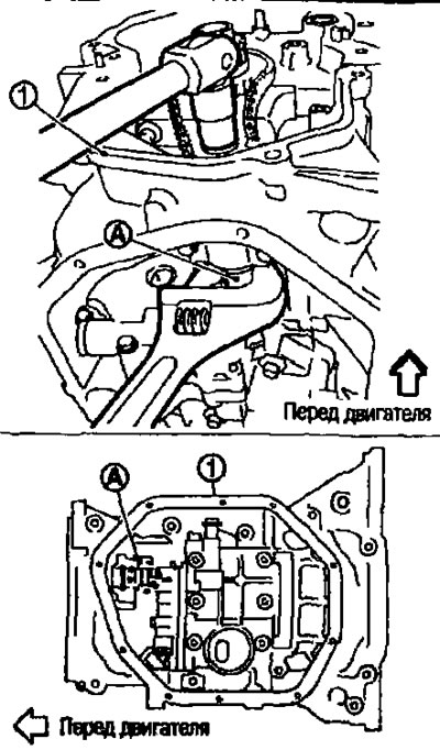
1. Oil pan (upper).
Attention:
- Fix the balancing unit shaft by the hexagonal part.
- Do not loosen the balancer block sprocket bolt while tightening the balancer block drive target.
e. Remove the crankshaft sprocket, balancer unit sprocket and balancer unit drive chain as a set.
17. If necessary, remove the timing chain tensioner guide (from the front cover side) from the front cover.
Installation
Note: The illustration shows the relative positions of the alignment marks on the chains and on the corresponding sprockets after the components have been installed.
1. Make sure the crankshaft key is facing straight up.
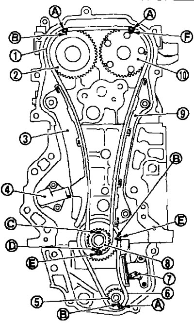
1. Timing chain; 2. Camshaft sprocket (outlet); 3. Chain guide at the bend; 4. Timing chain tensioner; 5. Balancing block sprocket; 6. Balancing block drive chain; 7. Balancing unit drive target tensioner; 8. Crankshaft sprocket; 9. Timing chain tensioner guide; 10. Camshaft sprocket (intake); A. Alignment mark (dark blue link); B. Alignment mark (stamped); C. Crankshaft key (facing straight up); D. Alignment mark (stamped); E. Alignment mark (orange link); F. Alignment mark (outer groove).
- There are two grooves on the periphery of the intake camshaft sprocket. The wider one is the alignment mark.
2. If the timing chain tensioner guide was removed (from the front cover side) install it into the front cover.
Caution: Make sure the components engage by sound or feel.
3. Install the crankshaft sprocket (2), the balancing unit sprocket (3) and the balancing unit drive chain (1).
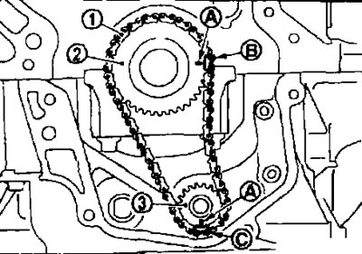
A. Alignment mark (stamped).
B. Alignment mark (orange link).
C. Alignment mark (dark blue link).
- Perform the installation by aligning the marks on all sprockets and on the balancer unit drive chain.
- If the marks do not align, slightly rotate the balance shaft and align.
Caution: Make sure that the alignment marks on the sprockets have not shifted after installing the balancer unit drive chain.
4. Fix the balance shaft by the hexagonal part (19.0 mm) (A) and tighten the balance block sprocket bolt.
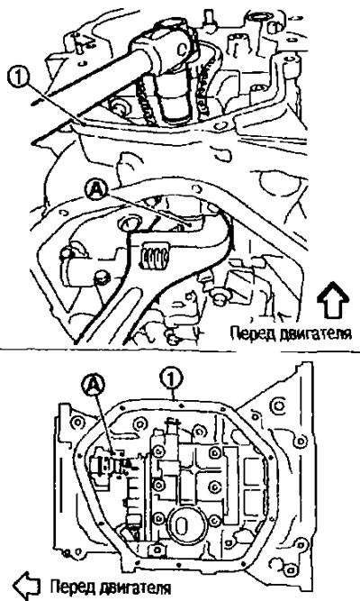
1. Oil pan (upper).
Attention:
- Fix the balancing unit shaft by the hexagonal part.
- Do not loosen the balancer unit sprocket bolt while tightening the balancer unit drive chain.
5. Install the balancing unit drive chain tensioner (1).
- Press the plunger in and hold it in the depressed position using the locking pin (A) to install the tensioner.
- After installing the balancer unit drive chain tensioner, carefully remove (
 ) locking pin.
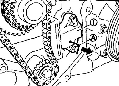
- Make sure that the alignment marks on the balancer drive chain and on the sprockets have not shifted.
6. Align the marks on each sprocket and timing chain.
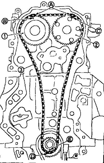
1. Camshaft sprocket (outlet); 2. Camshaft sprocket (intake); 3. Timing chain; A. Alignment mark (dark blue link); B. Alignment mark (stamped); C. Alignment mark (outer groove*); D. Alignment mark (orange link); E. Alignment mark (stamped).
*There are two grooves on the periphery of the intake camshaft sprocket. The wider one is the alignment mark.
- If the marks do not align, slightly rotate the camshaft by the hexagonal part and align them.
Caution: Make sure that the alignment marks on the sprockets have not shifted after installing the timing chain.
7. Install the timing chain tensioner guide (3) and the chain guide at the bend (2).
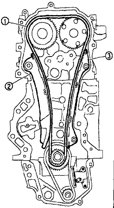
1. Timing chain.
8. Install the timing chain tensioner (1).
- Press the plunger in and hold it in the depressed position using the locking pin (A) to install the tensioner.
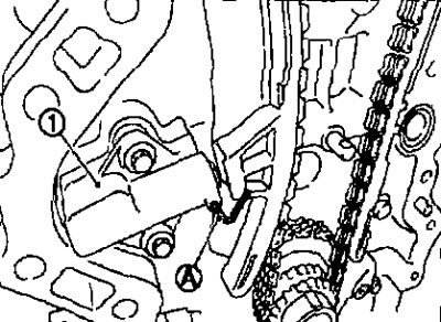
- With the timing chain tensioner installed, carefully remove the locking pin.
9. Check again that the alignment marks on the sprockets and timing chain have not shifted.
10. Press in the front oil seal. See below.
11. Install the front cover as follows:
a. Insert a new O-ring into the cylinder block.
Caution: Do not allow the O-ring to become displaced.
b. Apply sealant (B) in a continuous bead using a syringe (suitable special tools.) on the front cover as shown in the picture.
- Use brand name sealant or equivalent.
c. Make sure the timing chain and sprocket marks are still aligned. Then install the front cover.
Attention:
- Make sure the O-ring is inserted into the cylinder block correctly.
- Be careful not to damage the front oil seal on the front end of the crankshaft.
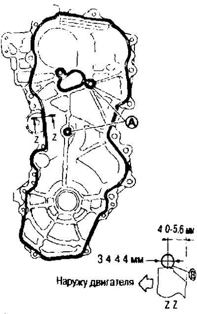
A. Sealant application area.
d. Install the front cover and tighten the mounting bolts in the order indicated by the numbers in the figure.
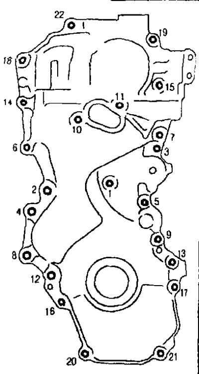
The bolt installation locations are shown below.
- M6: No.1.
- M10: No.6, 7, 10, 11, 14.
- M12: No.2, 4, 8, 12.
- M8: Except as noted above.
Caution: Installation must be performed within 5 minutes after applying the sealant.
e. After tightening the bolts, tighten them to the required torque in the order indicated by the numbers in the figure.
Caution: Remove any excess sealant that appears on the surface.
12. Install the crankshaft pulley as follows:
a. When pressing the crankshaft pulley with a plastic hammer, strike the center section (not in a circle).
Caution: Do not damage the lip of the front oil seal.
b. Secure the crankshaft pulley (1) with the pulley holder (A) (suitable special tool).
c. Apply fresh engine oil to the threads and seating surface of the crankshaft pulley bolt.
d. Tighten the crankshaft pulley bolt.
 : 68.6 N·m (7.0 kg·m).
e. Loosen completely.
 : 0 Nm (0 kg·m).
f. Tighten the crankshaft pulley bolt.
 : 29.4 N·m (3.0 kg·m).
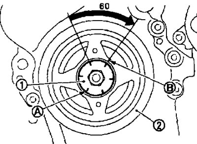
g. Place a paint mark (B) on the crankshaft pulley (2) opposite any of the six angle marks (A) on the flange (1) of the crankshaft pulley bolt.
h. Tighten the bolt 60° clockwise (tightening at an angle).
- Check the tightening angle using the angle marks.
i. Turn the crankshaft pulley clockwise by hand and make sure it rotates freely.
13. Install the remaining components in the reverse order of removal.
Check after removal
Timing chain
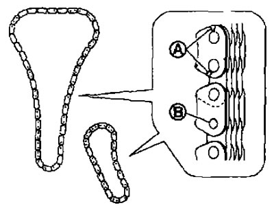
Check for cracks (A) or excessive wear (B) on the timing chain plates and roller links. Replace the timing chain if necessary.
Post-installation check
Checking for leaks
- Below are procedures for checking for fluid, engine oil and exhaust leaks.
- Before starting the engine, check the oil/fluid levels including engine coolant and engine oil. If the level is low, top up to the required level. See chapter "Maintenance".
- Check for fuel leaks as follows:
Turn the ignition key to the ON position (without starting the engine). After creating pressure in the fuel lines, check for fuel leaks at the joints.
Start the engine. Increase the engine speed and check again for fuel leaks at the fuel line joints.
- Let the engine run and check for any unusual noise or vibration.
Note: If the hydraulic pressure inside the timing chain tensioner drops after removal/installation due to slack in the guide, a dull knocking noise may occur when starting the engine and immediately after. However, this does not indicate a malfunction. The knocking noise will stop after the hydraulic pressure rises.
- Warm up the engine thoroughly and check for fuel or oil/fluid leaks, including engine oil and engine coolant.
- Bleed air from the tubes and hoses of the relevant systems, such as the cooling system.
- After the engine has cooled down, check the oil/fluid levels again, including engine oil and engine coolant. Top up as necessary to the proper level.
Check table
| Component | Before starting the engine | With the engine running | After the engine has stopped |
| Engine coolant | Level | Leakage | Level |
| Motor oil | Level | Leakage | Level |
| Other oils and liquids* | Level | Leakage | Level |
| Fuel | Leakage | Leakage | Leakage |
*Fluid for manual transmission, automatic transmission, CVT, power steering, brake fluid, etc.