


Table of contents: Removal ↓ Disassembly ↓ Removal and installation ↓ Disassembly and assembly ↓ Check after removal ↓ Checking after disassembly ↓ Post-installation check ↓
Removal
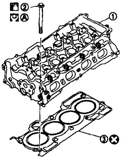
1. Cylinder head assembly; 2. Cylinder head bolt; 3. Cylinder head gasket. See below.
Disassembly
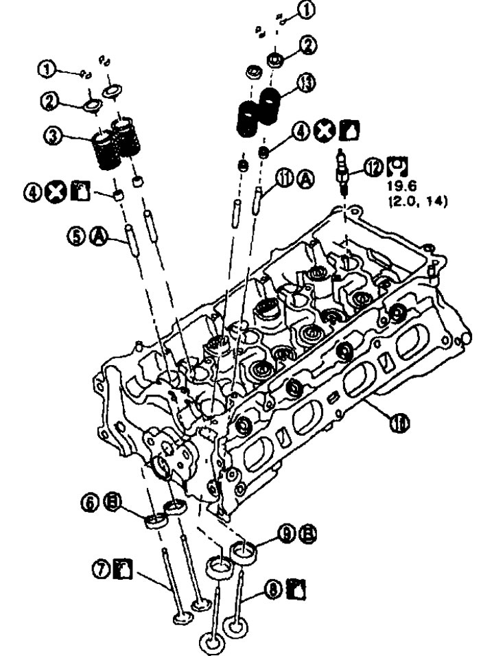
1. Rusks; 2. Valve spring plate; 3. Valve spring (exhaust) (with valve spring socket); 4. Valve seal; 5. Valve guide (outlet); 6. Valve seat (outlet); 7. Valve (release); 8. Valve (inlet); 9. Valve seat (intake); 10. Cylinder head; 11. Valve guide (intake); 12. Spark plug; 13. Valve spring (intake) (with valve spring socket); A. See below; B. See below.
Removal and installation
Removal
1. Relieve the fuel pressure. See chapter "Engine management system".
2. Drain the engine coolant and engine oil. See chapter "Lubrication system and engine cooling system".
3. Remove the following components.
- intake manifold; see above;
- intake manifold; see above;
- fuel injectors and fuel pipe assembly; see above;
- outlet pipe; see chapter "Engine lubrication system and cooling system";
- valve cover; see above;
- front cover timing chain see above;
- camshafts; see above.
4. Remove the cylinder head.
- Loosen the mounting bolts in the reverse order to that shown in the illustration.
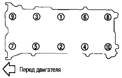
- Loosen the cylinder head bolts using a TORX head (size E18).
5. Remove the gasket from the cylinder head.
Installation
1. Place the gasket on the cylinder head.
2. Install the cylinder head and tighten the mounting bolts in the order indicated by the numbers in the figure as follows:
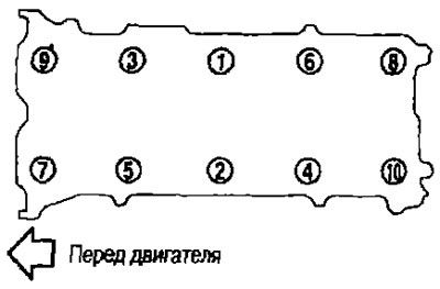
Caution: If reusing bolts, check their outside diameters before installation. See below.
a. Apply fresh engine oil to the threads and seating surface of the mounting bolts.
b. Tighten all bolts.
 . 40.0 N·m (4.1 kg·m)
c. Tighten all bolts 100° clockwise (tightening at an angle).
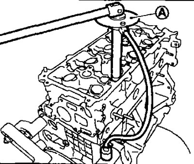
Caution: Check the tightening angle with a protractor wrench (special tool: KV10112100) (A) or a protractor. Avoid estimating by eye without using tools.
d. Loosen completely.
 0 Nm (0 kg·m).
Note: In step "d", loosen the mounting bolts in the reverse order to that shown in the figure.
e. Tighten all bolts.
 40.0 N·m (4.1 kg·m).
f. Tighten all bolts 100° clockwise (tightening at an angle).
g. Tighten all bolts another 100° clockwise (tightening at an angle).
3. After this operation, installation is performed in the reverse order of removal.
Disassembly and assembly
Disassembly
1. Remove the spark plugs using a wrench (suitable special tool).
2. Remove the valve lifters.
- Mark the locations and stack the components in order without mixing them.
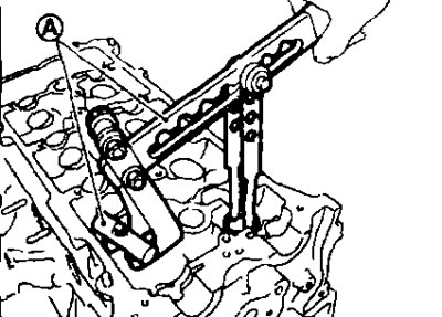
3. Remove the crackers.
- Compress the valve spring using a tool, attachment and adapter (special tool KV10116200) (A) Remove the crackers using a finger magnet.
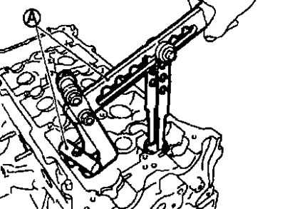
Caution: When performing work, do not damage the hole for the valve tappets.
4. Remove the valve spring retainer and valve spring (with valve spring socket).
Caution: Do not remove the valve spring seat from the valve spring.
5. Press the valve stem towards the combustion chamber and remove the valve.
- Mark the locations and place the components in order without mixing them.
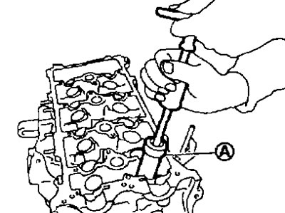
6. Remove the valve seal using a puller (special tool KV10107902) (A).
7. If it is necessary to replace the valve seat.
Drill out the old seat before it breaks. Drilling should not go deeper than the bottom of the seat recess in the cylinder head. For this purpose, place a depth stop on the drill. See the section below "Technical data and specifications".
Caution: Do not scratch the cylinder head by excessive drilling.
8. If the valve guide needs to be replaced:
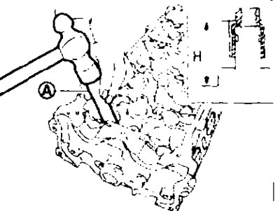
a. Remove the valve guide by heating the cylinder head to 110-130°C by immersing it in hot oil (A).
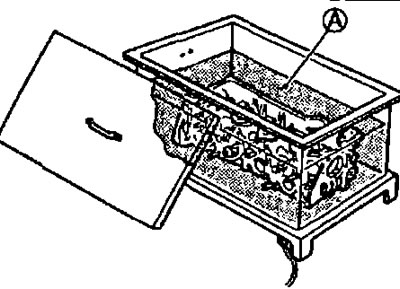
b. Knock out the valve guide using a hammer and punch (suitable special tool).
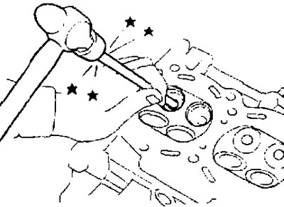
Caution. The cylinder head is hot. Wear protective clothing to avoid getting burned while performing work.
Assembly
1. If the valve guide was removed, install it.
Note: Replace it with a guide of increased repair size (by 0.2 mm).
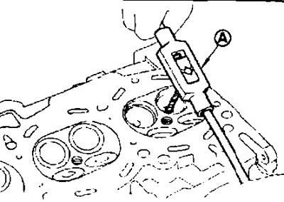
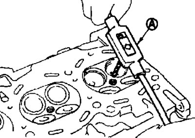
a. Ream the valve guide hole in the cylinder head using a reamer (suitable special tool) (A) (see fig.).
- Valve guide bore diameter (increased by 0.2 mm repair size), see below section "Technical data and specifications".
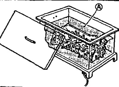
b. Heat the cylinder head to 110-130°C by immersing it in hot oil (A).
c. Press in the valve guide bushing (1) from the camshaft side, using the dimensions shown in the figure.
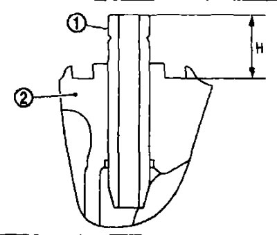
2. Cylinder head.
"H" protrusion: See "Technical data and specifications" section below.
Caution. The cylinder head is hot. Wear protective clothing to avoid getting burned while performing work.
d. Using a reamer (suitable special tool) (A) Finish the valve guide surface.
Standard: See "Technical data and specifications" section below.
2. If the valve seat was removed, install it.
Note: Replace it with a valve seat of increased repair size (by 0.5 mm).
a. Ream the recess (1) in the cylinder head for the repair size valve seat.
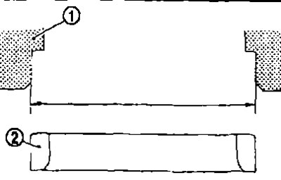
2. Valve seat.
The diameter of the recess in the cylinder head for the valve seat (increased by 0.5 mm repair size): see below section "Technical data and specifications".
- Ream in concentric circles toward the center of the valve guide. This will ensure proper seating of the valve seat.
b. Heat the cylinder head to 110-130°C by immersing it in hot oil (A).
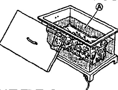
c. Cool the valve seats thoroughly with dry ice. Press the valve seats into the cylinder head.
Attention.
- Do not touch cold saddles with bare hands.
- The cylinder head is hot. Wear protective clothing to avoid getting burned while working.
d. Bring the seat to the required dimensions by milling or grinding with a suitable special tool. See the dimensions below in the section "Technical data and specifications".
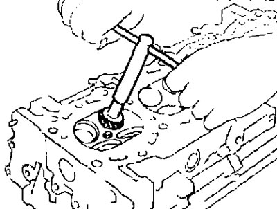
Caution: When milling the surface, grasp the handle with both hands. Then press the milling cutter against the contact surface along the entire circumference and mill in single passes. If the tool is pressed unevenly or with a break, the valve seat may take a stepped shape.
e. Grind the valve using grinding paste.
f. Recheck the valve fit. See below.
3. Press in the valve seal.
- Press in the valve seal using a punch (special tool KV10115600) (A) according to the dimensions shown in the figure.
Note: Dimension "H" is the height measured before installing the valve spring (with valve spring socket).
Height "H": 15.1-15.7 mm.
4. Install the valve.
- Install larger diameter valves on the intake side.
5. Install the valve spring (with valve spring socket).
- Install the spring with the side with the narrow pitch of the coils (side of the valve spring seat) to the cylinder head (B).
- Check the color marking of the valve spring(A).
Inlet: green color.
Issue: purple color.
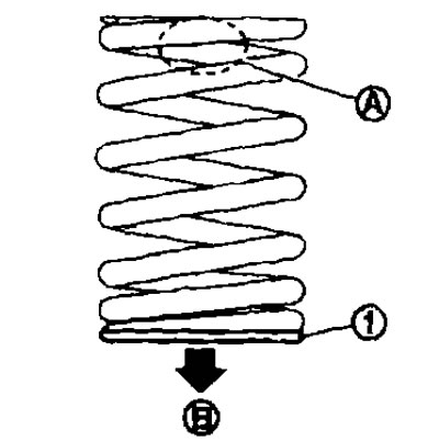
1. Valve spring seat (do not remove from valve spring).
6. Install the valve spring retainer.
7. Install the crackers.
- Compress the valve spring using a tool, attachment and adapter (special tool KV10116200) (A) (See Fig.) Place the crackers using a finger magnet.
Caution: When performing work, do not damage the holes for the valve tappets.
- After installing the valve components, lightly tap the tip of the valve stem with a plastic hammer to ensure proper seating.
8. Install the valve lifters.
- Install them in their original position.
9. Screw in the spark plugs using a wrench (suitable special tool).
Check after removal
Outside diameter of cylinder head bolts.
- The cylinder head bolts are tightened using the plastic zone method. If the difference between "d1" and "d2" exceeds the limit value, replace the bolts with new ones.
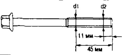
Limit "d1" - "d2": 0.15 mm.
- If the outside diameter narrowing is found at a location other than "d2", mark it as point "d2".
Cylinder head warping
Note: When performing this check, you should also check for warpage in the cylinder block. See the section below "Technical data and specifications".
1. Wipe off the oil and use a scraper to remove scale, gasket residue, sealant and carbon deposits from the surface of the cylinder head.
Caution: Do not allow gasket residue to enter the engine oil or coolant supply passages.
2. Using a ruler (A) and feeler gauge (B), check whether the lower surface of the cylinder head is warped by measuring in six directions.
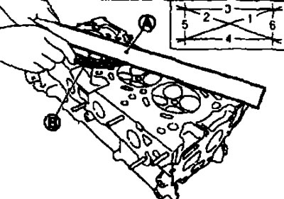
Limit: See below section "Technical data and specification".
- If warpage exceeds the limit, replace the cylinder head.
Checking after disassembly
Valve dimensions
- Check the dimensions of all valves. See the dimensions below in the section "Technical data and specifications".
- If the dimensions are different from the standard, replace the valve and check the valve seat contact patch.
Valve guide clearance
Valve stem diameter.
Measure the valve stem diameter with a micrometer (A).
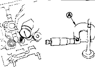
Standard: See below section "Technical data and specifications".
Inner diameter of valve guide bushing.
Measure the inside diameter of the valve guide bushing with a bore gauge.
Standard: See below section "Technical data and specifications".
Valve guide bushing clearance.
(Valve guide clearance) - (valve guide inner diameter) - (valve stem diameter).
Standard and Limit: See below section "Technical data and specifications".
- If the reading obtained exceeds the limit, replace the valve and/or valve guide. If the valve guide needs to be replaced, see the Disassembly and Assembly section above.
Valve seat contact patch
- Perform this check after making sure that the valve guides and valves are within normal dimensions.
- Apply red lead (or lead white) non-contact surface of the valve seat and check the fit of the valve to the seat.
- Make sure that the lead imprint appears around the entire circumference without any breaks.
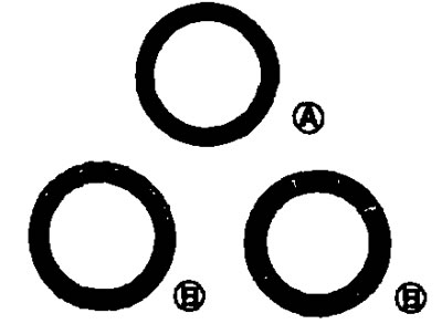
A. Normal; B. Abnormal
- Otherwise, achieve the required degree of valve seating by regrinding it and recheck. If the contact surface is still in poor condition even after rechecking, replace the valve seat. See above.
Valve spring squareness
- Place the angle (A) on the valve spring and rotate the spring. Measure the maximum gap between the top of the spring and the angle.
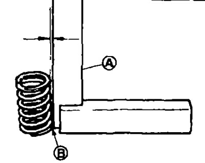
B. Point of contact
Limit: See below section "Technical data and specifications".
- If the clearance exceeds the limit, replace the valve spring.
Valve spring dimensions and compression force
- Check the valve spring compression force with the seat installed at the standard spring height.
Caution: Do not remove the valve spring seat from the valve spring.
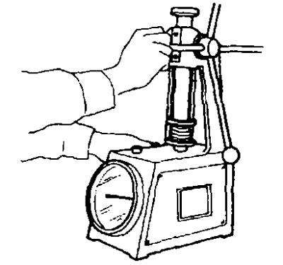
Standard: See "Technical data and specifications" section below.
- If the load after installation or with the valve open differs from the norm, replace the valve spring (with valve spring socket).
Post-installation check
Checking for leaks
- Below are procedures for checking for engine oil and exhaust fluid leaks.
- Before starting the engine, check the oil/fluid levels including engine coolant and engine oil. If the level is below the norm, top up and bring it to the required level. See chapter "Maintenance".
- Check for fuel leaks as follows: Turn the ignition switch to the ON position (without starting the engine). After pressurizing the fuel lines, check for fuel leaks at the joints. Start the engine. Increase the engine speed and check again for fuel leaks at the fuel line joints.
- Let the engine run and check for any unusual noise or vibration.
- Warm up the engine thoroughly and check for any leaks of fuel, exhaust gases or oil fluids including engine oil and engine coolant.
- Bleed air from the pipes and hoses of the relevant systems, such as the cooling system.
- After the engine has cooled, check the oil/fluid levels again, including engine oil and engine coolant. Top up as necessary to the proper level.
[The article was obtained from the portal nissanbook]
Check table
| Component | Before starting the engine | With the engine running | After the engine has stopped |
| Engine coolant | Level | Leakage | Level |
| Motor oil | Level | Leakage | Level |
| Other oils and liquids* | Level | Leakage | Level |
| Fuel | Leakage | Leakage | Leakage |
| Exhaust gases | — | Leakage | — |
* Fluid for manual transmission, automatic transmission, CVT, power steering, brake fluid, etc.