


Camshaft Installation Components
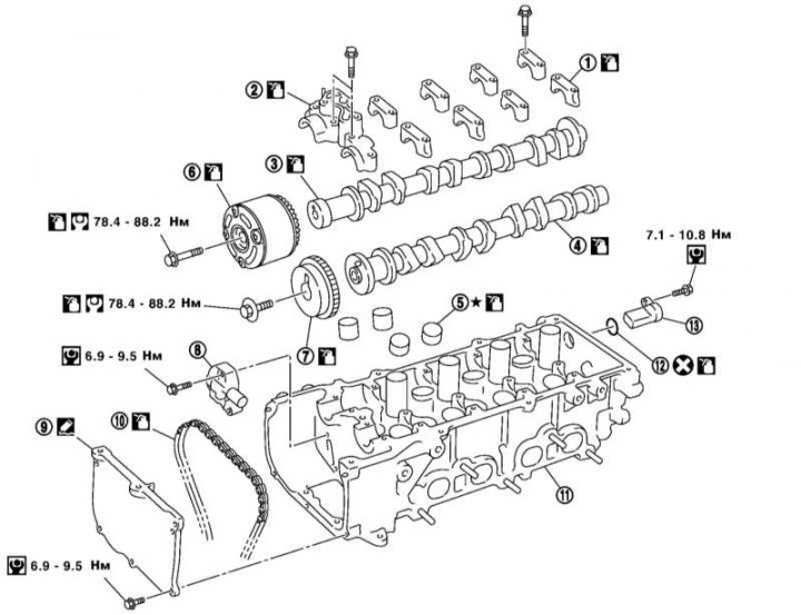
1 - Upper supports No.2-5 of camshafts; 2 - Upper support No.1 of camshafts; 3/4 - Inlet/outlet camshaft; 5 - Valve lifters; 6/7 - Inlet/outlet camshaft sprocket; 8 - Timing chain tensioner; 9 - Front cylinder head cover; 10 - Timing chain; 11 - Cylinder head; 12 - Sealing ring; 13 - Camshaft Position (CMP) Sensor
Removal
1. Remove the right front wheel arch liner (see Chapter Body).
2. Support the engine by installing lifting eyes on it and lifting it with a winch. Alternatively, support the engine with a jack. Remove the right engine mount strut and the right engine mount upper bracket (see section Removal and installation of the power unit).
3. Remove the cylinder head cover (see section Removal and installation the cylinder head cover).
4. If necessary, remove the CMP sensor from the rear of the cylinder head.
Note: Handle the sensor with care; its end is magnetic, so do not allow metal particles to stick to it.
5. Remove the right headlight (see Chapter On-board electrical equipment).
6. Remove the front cylinder head cover.
7. Set the piston of the first cylinder to the TDC position of the compression stroke, as described in paragraphs 8 through 10.
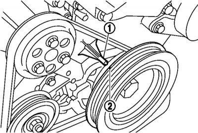
8. Turn the crankshaft pulley clockwise until the TDC mark (2) on the pulley aligns with the TDC indicator (1) on the front cylinder block cover.
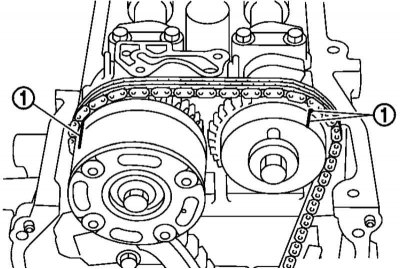
9. Make sure that the TDC marks on the camshaft sprockets are positioned as shown in the illustration. If not, rotate the crankshaft pulley one more revolution.
10. Once the TDC marks on the camshaft sprockets are positioned as shown in the illustration above, apply the corresponding marks on the timing chain links with paint or a marker.
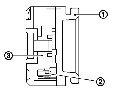
11. Removal and installation of the intake camshaft sprocket assembly should only be performed if the valve timing adjuster is in the maximum advance position. When the engine is not running, the adjuster (3) is in the maximum retard position and does not rotate, as it is locked on the sprocket (1) by the internal pin (2). If the intake camshaft sprocket assembly mounting bolts are loosened or tightened in the situation described above, the internal pin will be damaged, which will result in malfunctions due to increased horizontal load on the pin. To set the sprocket assembly to the maximum advance position, follow the procedures described in paragraphs 12 through 15. In this case, the timing chain tensioner must not be removed.
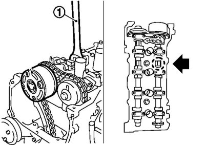
12. Place a wrench on the hexagonal portion of the intake camshaft and use it to prevent the shaft from turning.
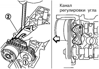
13. Using a hand pump (2) connected to the oil channel for adjusting the phases of the intake valves on the upper surface of support No.1 of the camshafts, create pressure not less than 3 atm, to bring the pin to the unlocked position. Maintain pressure while performing the procedures below.
14. Slowly turn the intake camshaft counterclockwise, looking from the front of the engine, i.e. in the direction of the intake manifold. As soon as a click is heard from the sprocket assembly, indicating that the phase adjuster is unlocked, or the adjuster begins to rotate independently on the sprocket, turn the camshaft in the opposite direction (to the exhaust pipe), to set the maximum advance position of the valve timing adjuster. If the unlocking does not occur, lightly shake the key holding the camshaft, or very carefully tap the front of the camshaft with a plastic hammer.
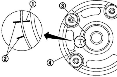
15. The phase regulator is in the maximum advance position, when it can rotate freely, and the sprocket rotates together with the camshaft. In this case, the mark (1) of the regulator (3) must coincide with the mark (2) of the sprocket.
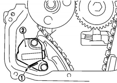
16. Insert a paper clip (1) into the timing chain tensioner (2) to lock the tensioner rod in the fully compressed position, and then remove the tensioner.
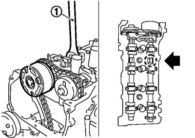
17. Holding the camshaft by the hexagon, unscrew the camshaft sprocket mounting bolts and remove the sprockets. When removing the intake camshaft sprocket, do not allow the phase adjuster to rotate so that it does not lock in the maximum retard position. Do not subject the intake camshaft sprocket assembly to force or disassemble it (do not remove the 4 front bolts).
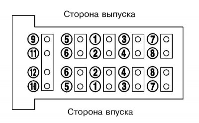
18. Remove the upper camshaft bearings by unscrewing the bolts in the following sequence:, reverse shown in the illustration.
19. Remove the camshafts, being careful not to deform the signal plate on the rear end of the intake camshaft.
20. Remove and position the valve lifters so that they can be reinstalled in their original locations.
Examination
1. Place the camshaft with journals No.2 and No.5 in the grooves of a special stand and, rotating the shaft, measure the radial runout of journal No.3. Compare the result obtained with the requirements Specifications and replace the shaft if necessary.
2. Measure the camshaft lobe height and camshaft journal diameter with a micrometer. Record the data obtained. Install the upper camshaft bearings and measure the inner diameter of their bearings formed by the upper bearings and the grooves in the cylinder head. Subtract the diameter of the corresponding journal from the inner diameter of each camshaft bearing to calculate the clearance values for each journal in the bearing. Install the shafts on the cylinder head and check their axial clearance by moving the shafts back and forth by hand. Compare the results with the requirements Specifications and, if necessary, replace the camshaft and/or the cylinder head assembly with the upper camshaft bearings.
3. Place the camshaft with journals No.2 and No.5 in the grooves of a special stand and, rotating the shaft, check the axial runout of its sprocket. Compare the obtained value with the requirements Specifications and replace the sprocket if necessary.
4. Check the outer surfaces (cylindrical and flat) valve tappets for cracks and signs of wear. Measure the outside diameter of each tappet and the inside diameter of the corresponding groove in the cylinder head. Subtract the first value from the second to calculate the clearance of each valve tappet in the seat. If necessary, replace the tappet or the cylinder head assembly with the upper camshaft bearings.
Installation
1. Install the valve lifters in their original locations.
[The article was obtained from the portal NISSANBOOK.ru]
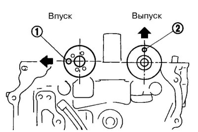
2. Clean the lower bearing surfaces of the camshafts (on the cylinder head) and install them, aligning the hole (1) on the intake shaft and the pin (2) on the exhaust shaft as shown in the illustration.
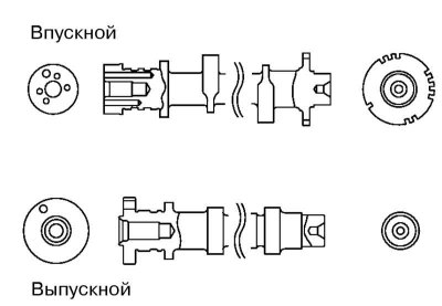
3. The intake shaft can be distinguished from the exhaust shaft by looking at their ends. In addition, on the camshafts between the cams of cylinders No.2 and No.3 (1.0 l and 1.2 l engines) or #3 and #4 (1.2 l and 1.4 l engines) there are color marks: green on the intake shaft and white on the exhaust shaft (1.0L engine) or red (1.2 l and 1.4 l engines).
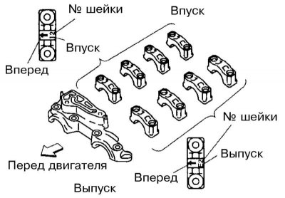
4. Clean the working surfaces of the upper camshaft supports and install them in their original places. The arrows on the supports should point towards the front of the engine (timing chain). The supports can be identified by the marks applied to them: the letter I or E means belonging to the intake or exhaust shaft, respectively, and the number following the letter indicates the journal number of the shaft (numbering starts from the timing chain).
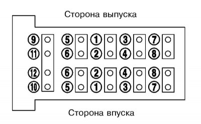
5. Tighten the upper camshaft support bolts: first – No.9-12 with force 2.0 Nm, then all the bolts in the specified sequence with force 5.9 Nm, and finally tighten all the bolts in the specified sequence with force 9.0÷11.8 Nm.
Note: The bolts are of different lengths and corresponding colors: No.1-10 are black, and No.11 and No.12 are gold.
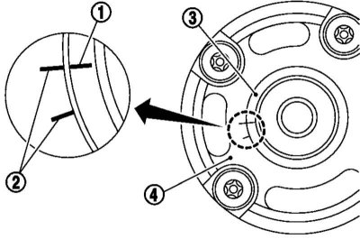
6. Install the intake camshaft sprocket assembly and make sure that the camshaft timing advance position marks match.
Note: The pin on the back of the sprocket assembly must fit into the corresponding hole on the shaft flange.
7. Install the timing chain onto the intake camshaft sprocket so that the mark on the chain aligns with the mark on the sprocket.
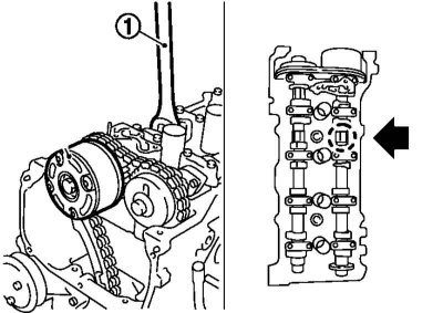
8. While holding the camshaft from turning, tighten the sprocket assembly mounting bolt and remove the tape securing the sprocket to the phase adjuster from the assembly (if installed).
9. Install the exhaust camshaft sprocket.
Note: The pin on the shaft flange must fit into the corresponding hole on the back of the sprocket.
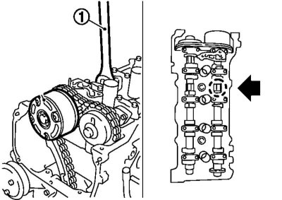
10. Install the timing chain on the exhaust camshaft sprocket so that the mark on the chain aligns with the mark on the sprocket. While holding the camshaft from turning, tighten the sprocket mounting bolt.
11. Make sure that the marks on the timing chain match the marks on the camshaft sprockets.
12. Install the timing chain tensioner and remove the paper clip inserted during removal. Once again, make sure that the marks on the timing chain match the marks on the camshaft sprockets.
13. Turn the crankshaft pulley clockwise to set the intake valve timing adjuster to the maximum retard position. When this position is reached, the adjuster and the intake camshaft sprocket should rotate simultaneously. Check that the adjuster is fixed in this position by turning the crankshaft pulley counterclockwise – the adjuster and the sprocket should rotate simultaneously.
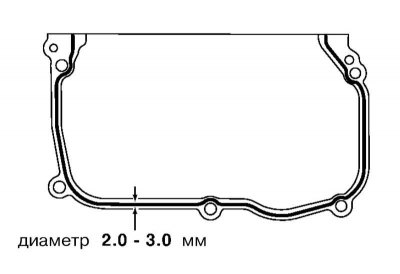
14. Apply a 2-3 mm diameter bead of sealant to the mating surface of the front cylinder head cover and install the front cover so that the holes in it coincide with the corresponding pins of the cylinder head.
15. Install the CMP sensor, making sure that its sealing ring and mating surfaces are clean.
16. Further installation is carried out in the reverse order of dismantling the components.