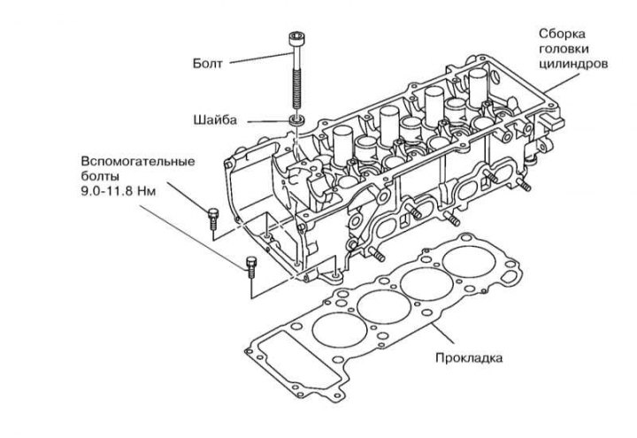
Removal and installation
Fastener of a head of cylinders
1. Relieve the pressure in the supply system (see Section Depressurizing the supply system).
2. Empty the cooling system (see Section Coolant replacement).
3. Remove the following components:
- Loker right front wheel arch;
- Belt of a drive of the generator and compressor K/V (see Section Replacing accessory drive belts and intermediate belt rollers);
- Air duct and air cleaner cover assembly (see Section Removal and installation of components of an inlet air path);
- Inlet pipeline (see Section Removal and installation of the inlet pipeline);
- Assembly of the fuel distribution line with injectors (see Section Removal and installation of injectors of fuel and the fuel distributive highway);
- Upper and lower radiator hoses (see chapter Engine cooling, heating, ventilation and air conditioning systems);
- Generator and its bracket (see chapter Engine Electrical Systems);
- Exhaust manifold with catalytic converter (see Section Removal and installation of the exhaust manifold, catalytic converter and lambda probe);
- Ignition coils (see Section Replacing spark plugs);
- cylinder head cover (see Section Removal and installation of a cover of a head of cylinders);
- Camshafts (see Section Removal, check and installation of camshafts);
- Lambda probe wiring bracket (see illustration Exhaust manifold and catalytic converter mounting components);
- Outlet pipe (thermostat cover), thermostat, ECT sensor, heater hose and coolant suction pipe (see chapter Engine cooling, heating, ventilation and air conditioning systems).
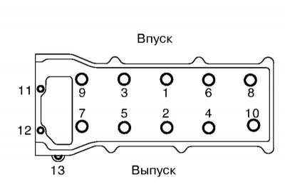
4. Turn out bolts of fastening of a head of cylinders in sequence, reverse indicated in the illustration.
5. Remove the cylinder head gasket.
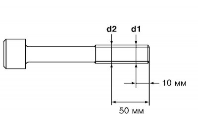
6. Measure diameter of a carving of bolts of fastening of a head of cylinders in the places specified in an illustration and subtract less from greater value. If the result is greater than 0.12 mm, replace the bolt.
If the minimum diameter d2 is not the minimum, use the minimum diameter instead of d2.
7. Apply sealant evenly to the areas shown in the illustration and install new cylinder head gasket.

8. Establish a head of cylinders and tighten bolts of its fastening in the sequence specified in an illustration, and in the sequence stipulated in Specifications.
Pre-lubricate the threads and the lower edges of the bolt heads with engine oil. When giving out the bolts in the second stage, unscrew them in reverse order. Auxiliary bolts (№№ 11-13) should only be tightened after the final tightening of the main bolts.
9. Further installation is carried out in the reverse order of the dismantling of the components.
Disassembly and assembly
Because disassembly and assembly of the cylinder head are typical procedures for all vehicles, only illustrations are given to explain the assembly of the cylinder head and some features.
Cylinder Head Assembly Components
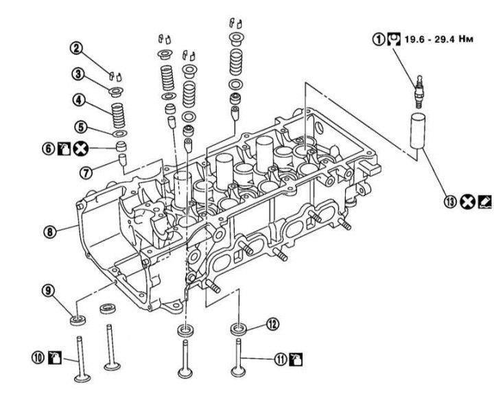
1 - spark plug; 2 - Valve crackers; 3/5 - Upper / lower plate of the valve spring; 4 - Valve spring; 6 - Oil deflector cap; 7 - Guide sleeve; 8 - Cylinder head; 9/12 - Inlet/outlet valve seat; 10/11 - Inlet / outlet valve; 13 - Spark plug bushing
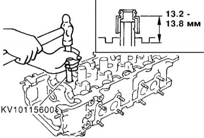
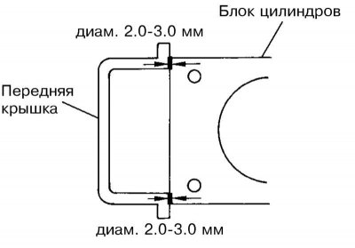
1. When installing the valve oil slinger cap, observe the dimensions shown in the illustration.
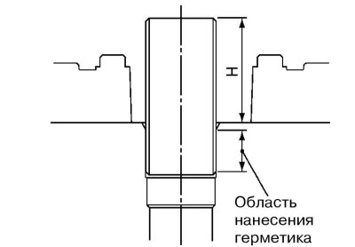
2. When installing the spark plug bushing, clean the mating surfaces of old sealant and apply sealant to the area shown in the illustration. Height (H) bushing protrusion should be 41÷42 mm.
3. After disassembling the cylinder head, check its parameters and the parameters of the valve mechanisms, guided by specifications. If necessary, replace defective valve seats and guides, the valves themselves or the cylinder head assembly with the upper camshaft bearings. A deformed cylinder head cannot be machined.