Note. Because disassembly and assembly of the cylinder block are typical procedures for all vehicles, only illustrations are given explaining the assembly of the block, and some features.
Cylinder Block Assembly Components
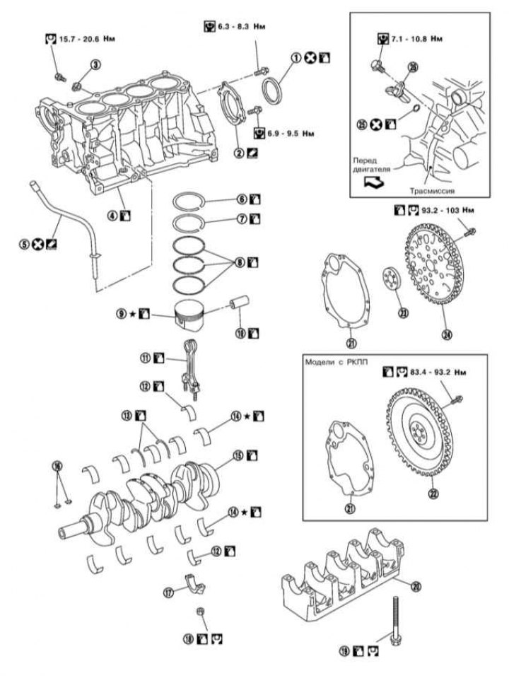
1 - Rear crankshaft oil seal; 2 - The holder of a back epiploon; 3 - Knock sensor (KS); 4 - Cylinder block; 5 - Guide for the engine oil level dipstick; 6/7 - Upper/lower compression ring; 8 - Oil scraper ring; 9 - Piston; 10 - Finger; 11 - Connecting rod; 12 - Connecting rod bearing; 13 - Thrust bearing; 14 - Main bearing; 15 - Crankshaft; 16 - Key; 17 - Connecting rod bearing cap; 18 - Connecting rod nut; 19 - Bolt of the main bearing cap; 20 - Main bearing cap; 21 - Back plate; 22 - Flywheel; 23 - Adapter; 24 - Drive disk; 25 - O-ring; 26 - CKP sensor
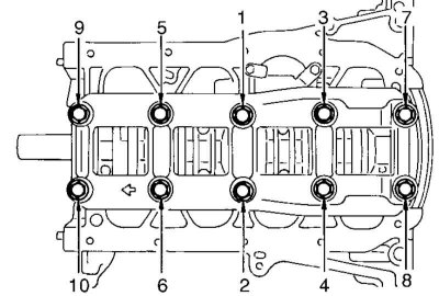
1. The sequence of a tightening of bolts of fastening of a cover of radical bearings of a cranked shaft is specified in an illustration.
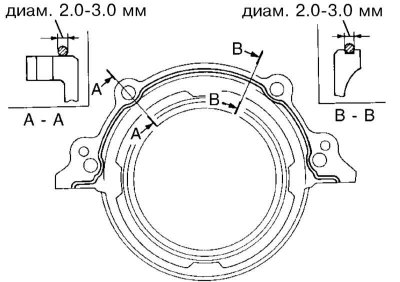
2. Places of application of sealant at installation of the holder of a back epiploon of a cranked shaft are specified on an illustration.
3. Data for checking the components of the cylinder block are given in Specifications.
4. When selecting pistons and main bearings, one should proceed from the size marks of the cylinders, the bed of the bearings and the crankshaft journals. The location of the marks is shown in the illustrations below.
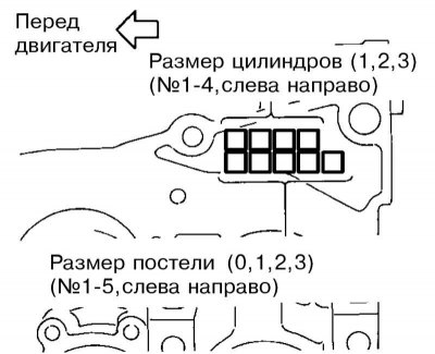
Cylinder and bearing bed size marks
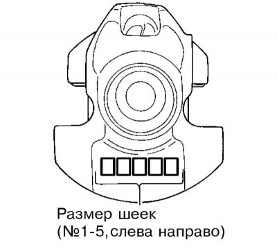
Crankshaft journal size marks