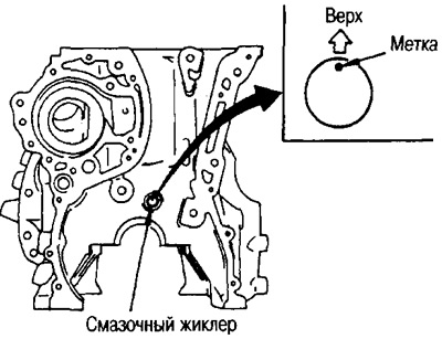
2. Install the oil jet for the timing chain.
Press it with the mark up into the front of the cylinder block.
3. Screw in all plugs and plugs.
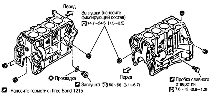
4. Establish an oil deflector on a back part of the block of cylinders.
Apply fixative sealant (Three Bond 1303) on the mounting bolts.
5. Install the main and thrust bearings.
Remove dust, dirt and oil from the contact surfaces under the bearings in the cylinder block and main bearing caps.
Apply engine oil to the inside surfaces of the bearings. Do not apply oil to the back of the bearing, but wipe it thoroughly.
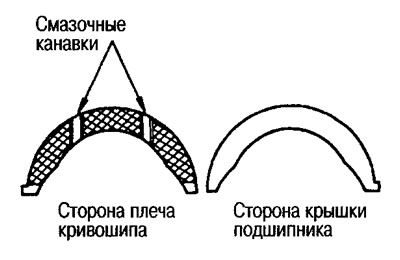
Insert the thrust bearing into the cylinder block with the oil groove towards the crank arm.
Install main bearings with lubrication holes and groove on the side of the cylinder block.
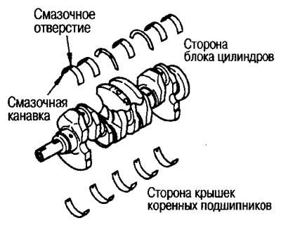
Install main bearings without lubrication holes and grooves on the side of the covers.
When installing, align the protrusion of the bearing with the notch.
Make sure the oil holes in the cylinder block and crankshaft line up with the holes in the bearings.
6. Install the crankshaft.
Turn the crankshaft by hand and make sure it turns freely.
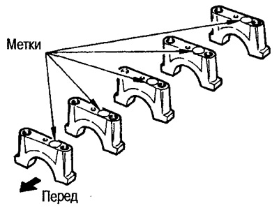
7. Install the main bearing caps.
Main bearing caps are marked in raised letters.
Covers are installed with markings on the right side.
Note: The cylinder block and main bearing caps are manufactured as one piece and must only be replaced as a set.
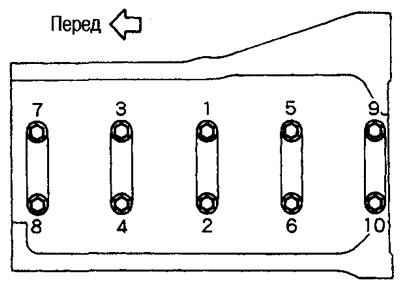
8. Tighten the mounting bolts in the order shown in the figure as follows.
- 1) Tighten to 6.9-13 Nm (0.7-1.3 kg m).
- 2) Tighten 75 -80°.
- 3) Fully loosen to 0 Nm (0 kg m) in reverse order.
- 4) Tighten to 32-38 Nm (3.3-3.9 kg m).
- 5) Tighten 30-35°.
The tightening angle is checked with a goniometer.
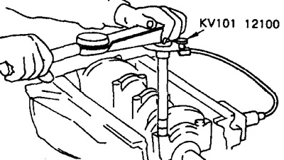
If no protractor wrench is available, mark the main bearing cap bolts (paint or others.) and check the tightening angle with a protractor.
Attention: Check the tightening angle with a goniometer or protractor. Avoid evaluation «approximately» without the use of tools.
After tightening the main bearing cap bolts, turn the crankshaft to make sure it turns freely.
Check crankshaft end play, see above.
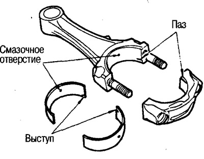
9. Insert the pistons into the connecting rods.
(1) Using circlip pliers, install the circlip into the groove on the back of the piston.
Insert the ring firmly into the groove.
(2) Install the piston into the connecting rod.
Using a hair dryer or similar device, heat the piston to 60-70"C, and insert the piston pin into the piston and connecting rod from the front of the piston towards the rear.
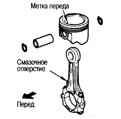
Assemble the piston and connecting rod so that the front mark on the piston crown and the oil hole on the connecting rod are located as shown in the figure.
(3) Install the circlip on the front of the piston.
After installation, make sure the connecting rod moves freely.
10. Install the piston rings using a piston ring expander.
Attention: Do not damage the piston.
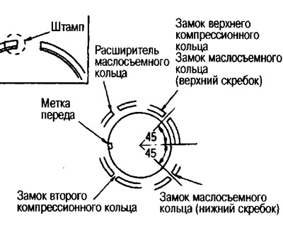
Install the top and second compression rings with the mark up.
Position the piston ring locks relative to the piston front mark as shown in the figure.
(3) Install the circlip on the front of the piston.
After installation, make sure the connecting rod moves freely.
10. Install the piston rings using a piston ring expander.
Attention: Do not damage the piston.
Install the top and second compression rings with the mark up.
Position the piston ring locks relative to the piston front mark as shown in the figure.
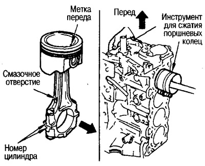
12. Install the piston and connecting rod assembly to the crankshaft.
Bring the crankpin of the connecting rod to be installed to BDC.
Check the cylinder number on the connecting rod and the position of the cylinder where the connecting rod will be installed.
Using a compressor to compress the piston rings, insert the piston with the front mark on the piston crown towards the front of the engine.
13. Tighten the connecting rod nuts as follows.
- (1) Apply engine oil to the bolt threads and connecting rod bearing nut seating surfaces.
- (2) Tighten the nuts with a force of 14-16 Nm (1.4-1.6 kg m).
- (3) Tighten the nuts by 60-65°.
Attention: Check the tightening angle with a goniometer or protractor. Avoid evaluation «approximately» without the use of tools.
If estimating the tightening angle is difficult, tighten the nuts to 38-44 Nm (3.9-4.5 kg m).
After tightening all nuts, make sure the crankshaft rotates freely.
Check the side clearance of the crankshaft connecting rod. See above section «Inspection - Connecting Rod Backlash».
14. Install the rear oil seal.
Installation is carried out in 2 stages in the following order.
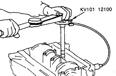
(1) By placing two punches for the rear oil seal (special tool) on top of each other, press in the rear oil seal with hammer blows (do not damage the seal).
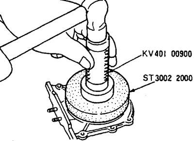
(2) Using one drift, press the oil seal flush with the front surface of the holder.
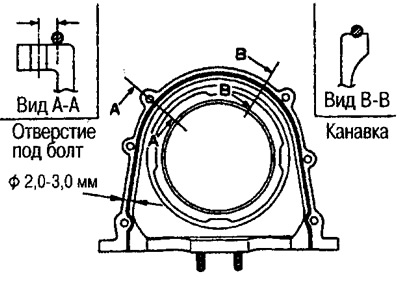
15. Install the rear oil seal retainer.
Apply Three Bond 1207C Sealant (KR51000150) continuous strip as shown.
16. Install the back plate.
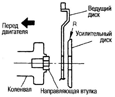
17. Install the drive disk.
Install the amplifying disk with the rounded edge on its outer circumference towards the driving disk.
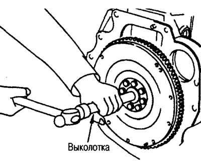
Secure the drive disc with the locking plate (special tool) and tighten the mounting bolt.
Caution: To prevent damage to the drive disc, place a cloth between the stop plate and the drive disc.
18. Install the guide bush (groove to crankshaft).
Drive in the guide bush with a drift with an outside diameter of approx. 34 mm.
19. Install the knock sensor.
Make sure that there are no foreign particles on the contact surface of the cylinder block and on the installation surface of the knock sensor.
Install the sensor 45°down from the right horizontal line towards the front of the engine.
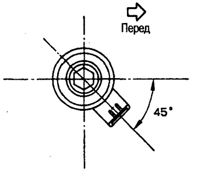
Do not apply excessive force to the connector while tightening.
After installation, the knock sensor must not interfere with other parts.
Caution: If you hit or drop the knock sensor, replace it with a new one.
20. Install the remaining parts in the reverse order of removal.