


Table of contents: Cylinder head warping ↓ Valve sizes ↓ Valve guide clearance ↓ Replacing the valve guide bushing ↓ Valve seat contact patch ↓ Replacing the valve seat ↓ Valve spring squareness ↓ Free length of spring, spring…↓
Cylinder head warping
Check the cylinder head underside for warpage at several points in six directions.
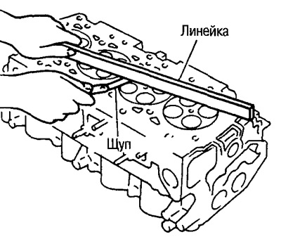
- Warpage Limit: 0.04 mm
Valve sizes
Use a micrometer to check the valve dimensions.
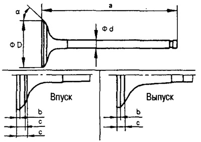
Standard valve sizes (mm):

Valve guide clearance
This check is performed before removing the valve guide.
Make sure the valve stem size is within specification.
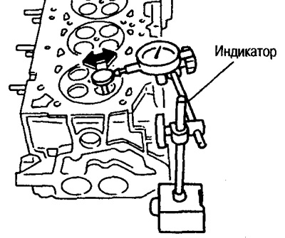
Press the valve into the combustion chamber approximately 25 mm, rock the valve towards the indicator and measure the amount of movement.
The valve guide clearance is ½ of the indicator reading.
Standard clearance:
- Intake: 0.020-0.053 mm
- Issue: 0.040-0.073 mm
Maximum clearance:
- Inlet: 0.08mm
- Issue: 0.1 mm
Replacing the valve guide bushing
In case of replacement of the valve guide bushing, a guide bushing of an increased (by 0.2 mm) repair size is installed.
(1) Heat the cylinder head to 110-130°C in an oil bath.
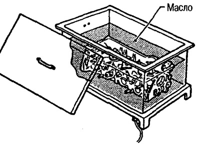
(2) Knock the valve guide out of the combustion chamber using a drift (for diameter 6 mm).

(3) Use a reamer to finish the surface of the hole for the valve guide bushing.
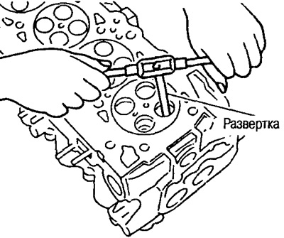
Standard reamed hole diameter:
- Inlet and outlet: 10.175-10.196 mm
(4) Heat the cylinder head to 110-130°C in an oil bath.
(5) Using a punch or press (for diameter 6 mm) press the valve guide into the bore on the camshaft side to obtain the dimensions shown in the figure.
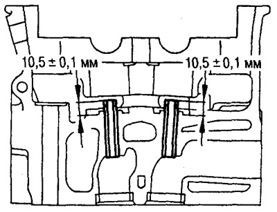
(6) After pressing the guide bushing, make a final reaming.
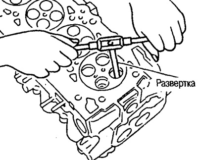
Standard hole diameter after final reaming:
- Inlet and outlet: 6.000-6.018 mm
Valve seat contact patch
Perform this check to ensure that the valve guides and valves are of proper size.
Apply PL-1 lead red lead to the contact surfaces of the seat and valve and check the uniformity of the valve fit to the seat during installation of the parts.
Make sure the print appears continuous around the entire circumference.
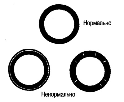
Otherwise, grind the valve and recheck the seating condition. If the recheck is negative, replace the valve seat.
Replacing the valve seat
When replacing a valve seat, a repair seat of an increased size (by 0.5 mm) is used.
(1) Drill out the old seat until the wall is very thin, then remove it.
(2) Ream the cylinder head seat recess to the following dimensions.
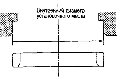
Standard size after unfolding:
- Intake: 30.500-30.516 mm
- Issue: 29,500-29,516 mm
(3) Heat the cylinder head in an oil bath to 110-130°C.
(4) Cool the valve seat with dry ice and press it into the cylinder block. Attention:
Do not touch cold saddles with bare hands.
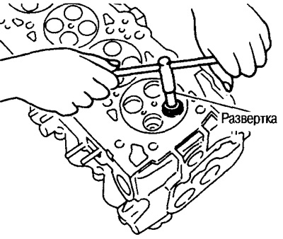
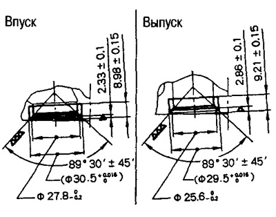
(5) Mill the saddle to the required dimensions.
Caution: When milling the seat, hold the tool handle with both hands so that the milling cutter touches the entire circumference and do the processing in one go. If the milling cutter is pressed incorrectly or installed several times, steps may appear on the valve seat.
(6) Grind the valve using grinding paste.
(7) Check the valve seating condition.
Valve spring squareness
Place the valve spring against the corner and, turning the spring, measure the maximum deviation of the upper part of the spring from the corner.
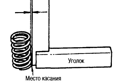
- Maximum non-squareness: 2.1 mm
Free length of spring, spring compression pressure
Measurements are taken using a special valve spring tester.
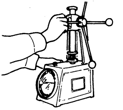
Standard spring parameters (mm):
