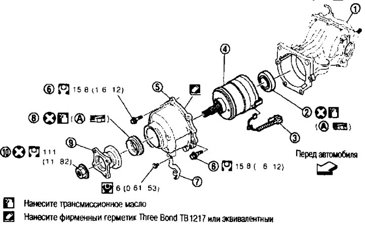
Engines MR20DE (manual gearbox, CVT) and OR25DE (manual gearbox) 1. Main gear assembly; 2. Central seal; 3. Solenoid wiring; 4. Clutch with electronic control; 5. Coupling cover; 6. Bolt; 7. Bracket for connector; 8. Front oil seal; 9. Connecting flange; 10. Locknut of connecting flange; A. Oil seal lip.
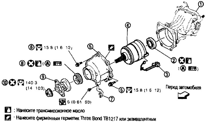
Engine QR25DE (CVT) 1. Main gear assembly; 2. Central seal; 3. 4WD Solenoid Wiring; 4. Electronically controlled clutch; 5. Coupling cover; 6. Bolt; 7. Bracket for connector; 8. Front oil seal; 9. Connecting flange; 10. Locknut of connecting flange; A. Oil seal lip.
Removal and installation
Removal
1. Remove the rear propeller shaft. See above.
2. Disconnect the connector from the 4WD solenoid.
3. Remove the bracket under the connector.
4. Place an alignment mark on the threaded end of the electronic coupling. The mark must match the mark on the coupling flange.
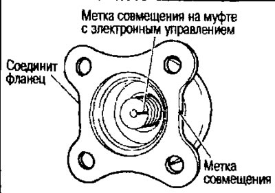
Caution: Apply marks with paint. Do not damage the electronically controlled clutch.
Note: When replacing an electronically controlled clutch, no marking is required.
5. Using a flange wrench (suitable special tool) unscrew the lock nut of the connecting flange.
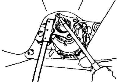
6. Remove the connecting flange.
7. Disconnect the electronic clutch breather hose from the clutch cover.
8. Remove the clutch cover with the electronically controlled clutch from the final drive assembly.
9. Remove the electronically controlled clutch from the clutch cover.
10. Remove the 4WD solenoid wiring.
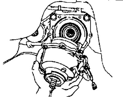
11. Remove the front oil seal from the clutch cover using a flat-blade screwdriver.
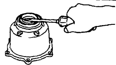
Caution: Do not damage the coupling cover.
12. Remove the center seal from the final drive assembly.
Installation
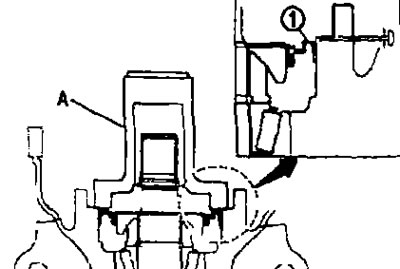
1. Using a punch (A) (special tool: ST35271000) press in the central seal (1) as shown in the figure.
Size "D": 0.8-1.2 mm
Attention:
- Do not reuse the seal.
- When pressing in, do not allow the seal to become skewed.
- Apply a universal consistent remover to the edges of the seal, and into the transmission oil - around the circumference of the seal.
2. Connect the 4WD solenoid wiring to the electronic clutch.
3. Insert the electronically controlled clutch into the spline of the pinion gear inside the differential housing.
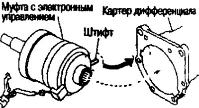
Attention:
- Align the pin on the electronic clutch with the groove in the differential housing.
- Do not damage the center seal.
4. Insert the 4WD solenoid wiring guide into the differential case.
5. Press in the front oil seal using a punch until it is flush with the end surface of the clutch cover.
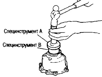
A. Vykolotka (special tool KV38100200); V. Vykolotka (special tool ST27861000)
Attention:
- Do not reuse the seal.
- When pressing in, do not allow the seal to become skewed.
- Apply universal grease to the lips of the seal, and apply transmission oil around the circumference of the seal.
6. Apply sealant to the contact surface of the coupling cover. Join both ends of the strip with an overlap of at least 3 mm.
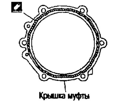
Caution: Remove old sealant from contact surfaces. Also remove moisture, oil or foreign particles from them.
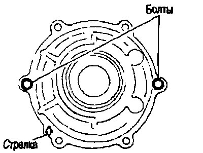
7. Install the clutch cover onto the final drive assembly with the arrow facing up, hand tighten the bolts in the locations shown in the figure.
8. Tighten the specified bolts and the clutch cover mounting bolts to the specified torque.
9. Connect the electronic clutch breather hose to the clutch cover.
10. Install the bracket under the connector and tighten the bolts to the required torque.
11. Connect the wiring connector to the 4WD solenoid.
12. Attach the connecting flange.
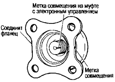
Note: When reusing the electronically controlled coupling, align the mark on the coupling with the mark on the coupling flange, then mate the coupling flange.
13. Using a flange wrench (suitable special tool) place the lock nut on the connecting flange and tighten to the required torque.
Caution: Do not reuse the coupling flange lock nut.
14. Check the runout of the connecting flange.
15. Attach the rear propeller shaft. See above.
16. If oil leakage was observed during removal, check the oil level after installation. See above.