


Table of contents: Removal and installation ↓ Checking the appearance ↓ Checking the runout ↓ Axial play of the hinge ↓ Central bearing ↓
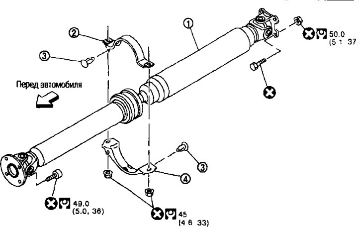
1. Cardan shaft assembly; 2. Center bearing mounting bracket (upper); 3. Clamp; 4. Center bearing mounting bracket (lower)
Removal and installation
Removal
1. Shift the transmission into neutral and release the parking brake.
2. Remove the following components:
- main muffler; see chapter "Accelerator, fuel system and exhaust systems";
- front exhaust pipe; see chapter "Accelerator, fuel system and exhaust systems" (MR20DE);
- central exhaust pipe; see chapter "Accelerator, fuel system and exhaust systems" (QR25DE).
Data copied from web resource NISSANBOOK.RU
3. Apply alignment marks to the fork of the rear propeller shaft connecting flange and the connecting flanges of the rear final drive and transfer case.
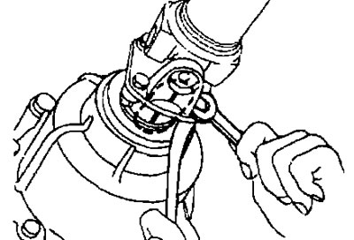
Caution: Apply marks with paint. Do not damage the fork of the rear propeller shaft connecting flange and the connecting flange of the transfer case.
4. Loosen the mounting nuts of the center bearing mounting brackets.
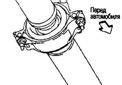
Caution: Tighten the mounting nuts by hand.
5. Unscrew the fastening bolts and nuts of the cardan shaft.
6. Loosen the mounting nuts of the center bearing mounting bracket.
7. Remove the propeller shaft assembly.
Attention. If you bend the constant velocity joint (CV joint) when removing, installing or carrying the driveshaft assembly, you could damage its boot. To protect the boot from breakage, wrap the areas where the boot touches the metal parts with a napkin or a piece of rubber.
8. Remove the clamps and remove the center bearing mounting bracket (upper/lower).
Installation
Installation is carried out in the reverse order of removal, taking into account the following:
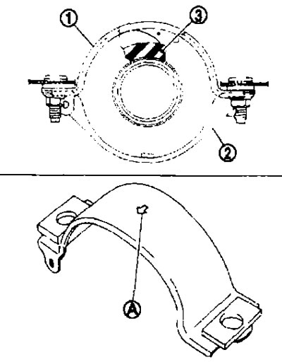
- Install the center bearing mounting bracket (upper) (1) with the arrow (A) facing forward.
- To prevent the center bearing insulator (3) from shifting longitudinally, adjust the position of the mounting bracket (1), (2) by moving it forward and backward. Install the center bearing mounting bracket (upper/lower) on the car.
- Align the marks, attach the cardan shaft to the connecting flanges of the main gear and transfer case.
- After assembly, perform a road test and check the propeller shaft runout. If runout is detected, separate the propeller shaft from the final drive. Re-fasten the coupling flange by rotating it 90, 180 and 270°. Then perform a road test again and check the propeller shaft runout at each point
- After tightening the bolts and nuts to the required torque, make sure that the bolts (3) on the connecting flange side are tightened as shown in the figure.
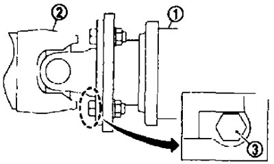
1. Main gear assembly; 2. Cardan shaft assembly.
If replacing the propeller shaft or final drive assembly, install them as follows:
- Turn the mark (A) on the connecting flange of the final drive (1) upward. Keeping the mark (A) upward, connect the propeller shaft to the final drive so that the mark (B) on the propeller shaft (2) can be positioned as close as possible to the mark (C) on the connecting flange of the final drive.
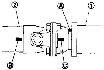
- Tighten the driveshaft and final drive mounting bolts and nuts to the specified torque.
Checking the appearance
Check the driveshaft for bending or damage. Replace the driveshaft assembly if necessary.
Checking the runout
Check the propeller shaft runout at the measurement points. If it exceeds the specified limit, replace the propeller shaft assembly. See the measurement points above.
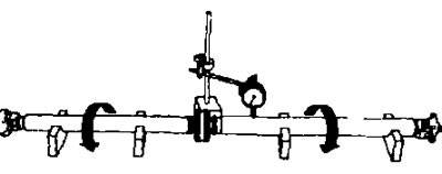
Limit runout See below section "Technical data and specifications".
Axial play of the hinge
Fix the fork of the connecting flange on one side as shown in the figure, check the axial play of the joint. If the play is different from the norm, replace the cardan shaft assembly.
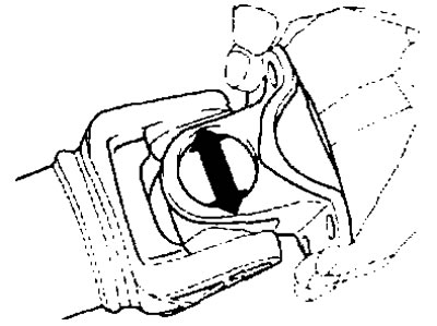
Standard hinge play. See section below "Technical data and specifications".
Attention. Do not disassemble the hinges.
Central bearing
If the center bearing is making unusual noise or is damaged, replace the driveshaft assembly.
Caution: Do not disassemble the center bearing.