


Note: Understanding the basics of electrical theory makes troubleshooting electrical equipment easier. Various electrical devices are used to diagnose faults in electrical equipment. Without understanding the basics, it will be difficult to understand measurement procedures.
Electricity is the flow of electrons, the hypothetical particles that form the basis of electrical "substance." Compared to water flowing through a pipe, electrons would be water. Since the flow of water can be measured (i.e. its characteristics), then the characteristics of the electron flow can be measured. The unit of measurement of current is ampere (A). An ammeter measures the amount of electricity flowing in a circuit per unit of time. Like water pressure, it is measured in units of Pa (Pascal), N/m² (Newton per square meter) just as electrical voltage is measured in volts (V), so too is electrical voltage. When two voltmeter leads are connected to two points in an electrical circuit with different electrical potentials, current flows through the voltmeter and produces a voltmeter reading, which indicates the difference in electrical potential between these two points in the circuit, i.e., voltage. As the voltage in the circuit increases, the current will also increase, which will depend not only on the voltage, but also on the resistance of the circuit. The unit of resistance is Ohm, which is measured with an ohmmeter. An ohmmeter is similar to an ammeter, but has its own voltage source, meaning it always provides a standard voltage. A real electrical circuit contains four main parts, the voltage source (generator or battery); a live wire that supplies a sufficiently high electrical voltage to consumers that are connected to the circuit; consumers - lamps, electric motors, resistors, relays; and a ground wire that carries the current back to the low voltage source. In such a circuit, there is resistance between the point where the live wire is connected to the consumer and the point where the load is grounded. In cars where the body is made of steel, it is used as a ground wire for most electrical wires.
Attention: Remember that when making electrical measurements, the voltmeter is connected in parallel to the circuit being tested (without disconnecting wires) and the voltage difference is measured between the two points where the voltmeter wires are located; the ammeter is connected in series with the consumer (the circuit is broken at one point and an ammeter is inserted there so that it becomes part of the circuit); and the ohmmeter is powered by its own source, so all power sources in the circuit must be turned off, and the part of the circuit to be measured must be connected to one of the ohmmeter leads.
For any electrical system to work, it must be a closed circuit, i.e. the voltage from the battery must form a closed circle. When electrical consumers work, the voltage comes to them from the battery, passes through the consumers, making them work (for example, the pampa glows) and then returns to the battery through the circuit ground. This ground is usually a metal part of the car to which these consumers of the circuit are attached.
Perhaps the easiest way to demonstrate this is to connect a light bulb with two wires to the battery terminals. There are two contacts on the battery - negative and positive. If one of the wires leading to the light bulb is connected to the negative pole of the battery, and the other wire to the positive pole, a closed circuit will be created. The current from the battery goes to the terminal, from the terminal through a wire goes to the light bulb, passes through the light bulb, another wire and returns to the other terminal of the battery.
A normal car wiring diagram differs from this example in two ways. First, instead of a wire that carries current back to the battery from the light bulb, the car uses the car body. Since the negative battery terminal wire is connected to the car body, which is made of a metal that conducts electricity, the car body can serve as a ground wire to complete the circuit. Secondly, most automotive circuits contain switches for connecting and disconnecting consumers.
Some electrical consumers that require a lot of current to operate also have a relay in their circuit. Since these devices consume a lot of current, the thickness of the wires supplying voltage to them must also be larger.
If large wires were run from the consumer circuit to the control switch on the dashboard and then connected back to the consumer, there would be a voltage drop in the circuit. To prevent this potential voltage drop, electromagnetic relays are used. Thick wires are connected from the battery to one side of the relay and from the other side of the relay to the consumer. In normal condition the relay is open (open) and prevents current from flowing through the circuit. In addition to this, thin wires run from the relay to the consumer's control switch. When the control switch is turned to the "on" position, the thin wire from the relay is grounded and the circuit is closed. If you were to disconnect the light bulb from our example, connected by two wires to the ends of the wires, and then connect the wires again (there is no need to do this), then you would see sparks. Such things happen when the wires supplying voltage to consumers or the consumers themselves are grounded differently than provided for in the circuit diagram. To prevent damage, fuses are connected to the circuit. Since accidental grounding of wires from a voltage source causes the circuit to become closed, depriving consumers of voltage, this phenomenon is called a short circuit. Its main causes are: damage to the insulation of wires or contact of bare wires with metal parts of the car, or a short circuit in the switch.
To carry out measurements on electrical equipment systems, so-called multimeters are available for sale. They combine in one device a voltmeter for measuring voltage, an ammeter for measuring current, and an ohmmeter for measuring resistance. Commercially available measuring instruments differ from each other mainly in their ranges and measurement accuracy. The measurement range determines the area in which the voltage or resistance value must be in order for it to be recorded by the measuring device.
For car enthusiasts, there are multi-range measuring instruments that are designed specifically for conducting electrical tests on the vehicle's electrical system. With a single device like this, you can measure engine speed, winding resistance, and voltages up to 20 V. When measuring resistance, the range is usually limited to a few kilo-ohms, meaning the measured resistance values should be between 1 and 1000 kOhm.
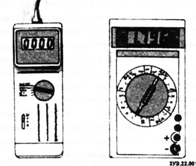
In addition, there are special measuring instruments for testing electrical and electronic components. These devices allow for resistance measurements over a wide range, from a few ohms to several milliohms. Voltages can be measured very accurately, which is essential when testing electronic components.
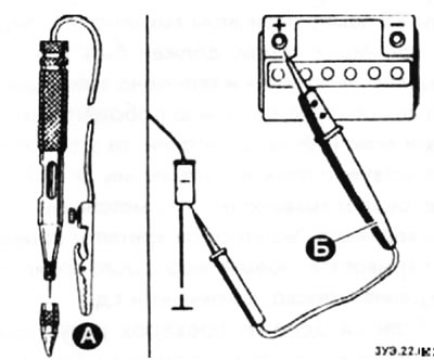
Caution: When checking electronic components (transistors, diodes and control units) a high-impedance voltage tester (B) is required. It works in the same way as a test lamp (A), but does not damage electronic components, making it suitable for all types of testing.
Voltage measurement
The presence of voltage can be checked using a simple test light or voltage tester. True, this can only determine whether there is voltage at all. To determine the voltage value, you need to use a voltmeter.
First of all, it is necessary to set the appropriate measurement range on the voltmeter, i.e. one in which the value of the measured voltage will be located. The voltage in a car's electrical system typically does not exceed 14 volts. The ignition system is an exception; the operating voltage supplied to the spark plugs can reach 30,000 V. Such high voltages can only be measured using special instruments.
For measuring devices intended for use on vehicles, you only need to turn the device on to the voltage measurement mode. A number of operations must be performed on the multimeter. First of all, you need to use the switch to select the DC voltage measurement mode. Then the measurement range is selected. Since high voltages are not used in a car except in the ignition system (DC voltage does not exceed 14 V), then the upper limit of the range used should be slightly higher (from 15 to 20 V). If you are confident that the measured voltage will be significantly less than the specified values, for example, about 2 V, then you can select the reduced voltage range to obtain more accurate results. If the voltage during measurements exceeds the maximum permissible for a given range, the device may fail.
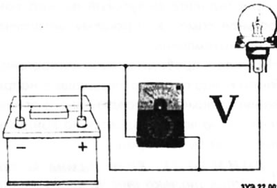
Connect the measuring instrument wires in parallel to the electrical consumer as shown in the figure. In this case, the red wire from the measuring device is connected to the wire coming from the positive (positive) terminal of the battery, the black wire from the device is connected to the wire connected to the ground or to a metal part, for example, the engine cylinder block.
Measurement example: If the engine does not start because the starter turns over too slowly, it is recommended to check the voltage on the battery while the starter is running. To do this, connect the red wire of the voltmeter (+) to the positive terminal of the battery, and the black wire of the voltmeter (-) to the ground of the car. The assistant should then turn on the starter and determine the voltage value. If the voltage is less than 10 V (battery temperature is about 20°C), then the battery must be checked and recharged.
Measuring current
In a car, it is quite rare to have to measure the current. This is necessary, for example, if the battery is discharged through some electrical consumer. For such measurements, an ammeter is required, which is also built into the multimeter.
Before measuring current, it is necessary to switch the device to a measurement range in which the measured current will be located. If the current value is unknown, it is necessary to switch on different measurement ranges in turn, starting with the maximum.
To measure current strength, it is necessary to break the current flow circuit and connect the measuring device (ammeter) into the open circuit. For such an operation, you can, for example, disconnect the plug and connect the red (positive) wire of the ammeter to the current-carrying wire. The black (negative) wire of the ammeter is connected to the contact from which the wire was disconnected. Contact with the ground between the consumer and the plug must be ensured using an auxiliary wire.
Caution: Never use a conventional ammeter to measure the current flowing to the starter (it is equal to approximately 150 A). When measuring such currents, the ammeter will immediately fail. In workshops, a non-contact method using a special clamp is used to measure such currents. When taking measurements, the clamp is placed on the insulation of the current-carrying wire, and the current strength is determined by induction.
Measuring resistance
Before measuring the resistance value, it is necessary to check that a fresh battery is installed in the ohmmeter and that voltage is not applied to the part whose resistance will be measured. For this reason, it is always necessary to disconnect the cables from the battery first. Otherwise, the measuring instrument may be damaged.
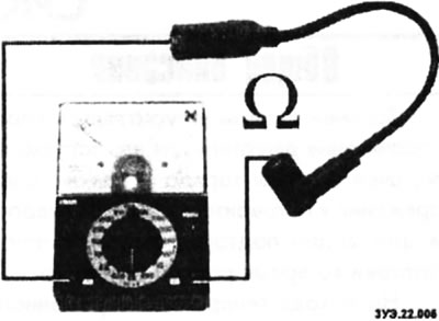
The ohmmeter is connected to two contacts of an electrical consumer or to two ends of an electrical wire. In this case, the polarity of the ohmmeter connection does not matter. The exceptions are the following: measuring the resistance of blocks that contain diodes. To check the functionality of the diode, it is necessary to connect an ohmmeter to it in the direction of direct conductivity.
Measuring resistance in a car is mainly done in two cases:
- Checking a resistor or other component included in the current flow circuit.
- Checking the continuity of an electrical wire, switch, or lamp filament. This checks to see if the electrical wire in the car is broken, and determines the reason why the electrical device to which this wire is connected does not work.
When taking measurements, the ohmmeter is connected to the ends of the corresponding wire. If the ohmmeter shows a resistance close to 0 ohms, then the wire is conductive, i.e. it is in good condition. If the wire has a break, the ohmmeter will show infinite resistance (∞ Ohm).