


Table of contents: Hydraulic circuit ↓ Removal and installation ↓ Installation ↓ Post-installation check ↓
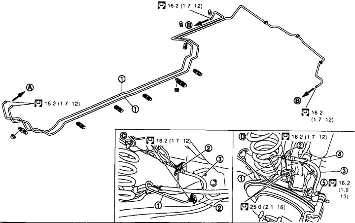
Rear disc brakes. 1. Brake pipe; 2. Locking plate; 3. Brake hose; 4. Brake hose bracket; 5. Connecting bolt; A. To the front wheel brake hose; B. To the rear wheel brake hose; C. From the floor side; D. From the caliper side.
Hydraulic circuit
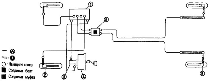
MR20DE engines (white ESP systems) and QR25DE (without ESP system). 1. ABS actuator and control unit; 2. Front disc brake; 3. Master cylinder assembly; 4. Brake booster; 5. Coupling; 6. Rear wheel disc brake; A. Brake pipe; B. Brake hose.
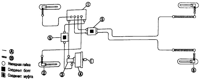
MR20DE engines (with ESP system) and QR25DE (with ESP system). 1. ABS actuator and control unit; 2. Front disc brake; 3. Master cylinder assembly; 4. Brake booster; 5. Coupling; 6. Rear wheel disc brake; A. Brake pipe; B. Brake hose.
Removal and installation
Removal
Caution: Do not spill brake fluid on painted areas; it may cause damage to the paintwork. If brake fluid spills on painted areas, wipe it off immediately and rinse with water.
(Source is available on the resource: NISSANBOOK.ru)
1. Remove the wheels.
2. Drain the brake fluid. See above.
3. Using a spanner, loosen the union nut and disconnect the brake pipe from the hose.
Attention:
- Avoid scratching union nuts and brake pipes.
- Avoid sharp bends, twists, or pulling on brake hoses and pipes.
- To prevent dust and other foreign particles from entering the brake fluid, plug the open ends of brake pipes and hoses when disconnecting them.
4. Loosen the connecting bolt and disconnect the brake hose from the caliper assembly.
5. Remove the locking plate and remove the brake hose from the vehicle.
Installation
Caution: Do not spill brake fluid on painted areas, as it may damage the paintwork. If brake fluid is spilled on painted areas, wipe it off immediately and rinse with water.
1. Place the connecting bolt and copper washers on the brake hose.
Caution: Do not reuse copper washers.
2. Connect the L-shaped metal fitting of the brake hose to the mounting hole on the brake caliper assembly and tighten the connecting bolt (1) to the specified torque.
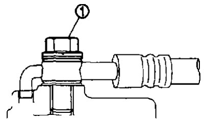
3. Connect the brake pipe to the brake hose, tighten the union nut by hand as much as possible, and secure the brake hose to the bracket with the lock plate.
Caution: Avoid sharp bends and twisting of brake hoses and pipes.
4. Using a torque wrench, tighten the union nut to the specified torque.
Caution: Do not scratch the union nuts and brake pipes.
5. Fill with fresh brake fluid and bleed air. See above.
Caution: Do not reuse drained brake fluid.
6. Install the wheels.
Post-installation check
1. Check: for scratches on the brake pipes and hoses; are they twisted or deformed?; do they touch other components when turning the steering wheel?; have the connections at the joints become loose?.
2. Check for fluid leaks from components by depressing the brake pedal for approximately 5 seconds with a force of 765 N (80 kg) at idle speed.
Caution: If brake fluid leakage is detected, tighten the components at the joints to the required torque or replace the faulty one (damaged, worn or deformed) component.