


Table of contents: Brake pads ↓ Removal ↓ Installation ↓ Brake caliper ↓ Checking the caliper ↓ Cylinder ↓ Brake caliper ↓ Guide pins with mounting bolts and…↓ Assembly ↓ Checking the brake disc ↓ Brake bedding-in ↓
Rear disc brake components
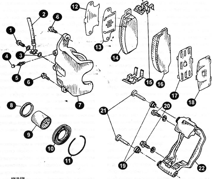
1 - connecting (hollow) bolt; 2 - brake hose; 3 - copper washer; 4 - cap; 5 - air bleed valve; 6 — guide pin mounting bolt; 7 — brake cylinder housing; 8 — piston cuff; 9 — piston; 10 — piston cover; 11 — fastening ring; 12, 13 - internal noise-absorbing pads; 13 - inner washer; 14 - inner brake shoe; 15 — brake shoe retainer; 16 - outer brake shoe; 17, 18 - external noise-absorbing pads; 19 — guide pin cover; 20 — brake caliper mounting bolt; 21 - guide pin; 22 — brake caliper.
Components of a front disc brake
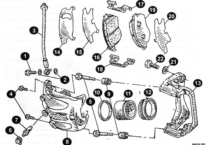
1 - connecting (hollow) bolt; 2 - copper washer; 3 - brake hose; 4 — guide pin mounting bolt; 5 - guide pin; 6 - cap; 7 — air bleed valve; 8 — brake cylinder housing; 9 — guide pin cover; 10 — piston cuff; 11 — piston; 12 — piston cover; 13 — brake caliper; 14 and 15 - internal noise-absorbing pads; 16 - inner brake shoe; 17 — brake shoe retainer (upper); 18 — brake shoe retainer (lower); 19 — outer brake shoe; 20 - external noise-absorbing gasket; 21 - washer; 22 — brake caliper mounting bolt.
Brake pads
Checking for wear
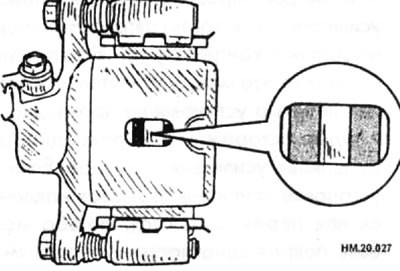
- Check the thickness of the working layer of the brake pads through the inspection hole (arrow) in the brake cylinder body. Use a ruler if necessary.
Brake pad sizes
| Brake pad type | ||
| CLZ31VB | AD14VE | |
| Nominal thickness | 9.5 mm | 8.5 mm |
| Maximum permissible thickness | 2.0 mm | 2.0 mm |
Caution: To reduce the risk of foreign particles getting inside the brake cylinder, clean the brake caliper and brake pads from dust using a vacuum cleaner.
- When removing the brake cylinder housing, do not press the brake pedal under any circumstances, otherwise the piston will jump out of the cylinder.
- There is no need to remove the brake caliper and brake hose mounting bolts unless the brake caliper is being disassembled or replaced. In this case, the cylinder body must be suspended on a wire so that the brake hose is not stretched.
- Do not damage the piston seal during operation.
- If any of the sound-absorbing pads are seriously damaged by corrosion, replace them with new ones.
- When replacing brake pads, always replace all noise-damping shims and washer covers. After resurfacing or replacing brake discs, replacing brake pads, or if the brake pedal feels soft for some time, it is necessary to bed in the contact surfaces of the brake pads.
Removal
- Remove the wheels from the car.
- Remove the lower guide pin mounting bolt.
- Hang the cylinder body on a wire and remove the brake pads and noise-absorbing linings from the brake caliper.
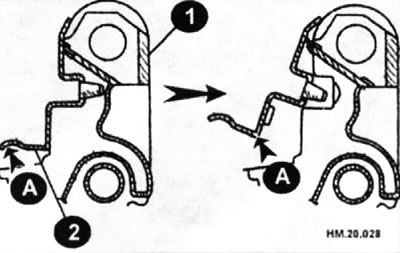
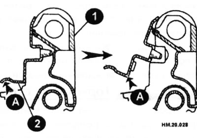
- When removing the brake shoe retainer (2) from the brake caliper (1), lift it in the direction shown by the arrow (A) in the figure, otherwise the retainer may be deformed.
Installation
- Attach the inner noise-absorbing pads to the inner brake shoe and the outer pads to the outer brake shoe, install the pad retainer and pads on the brake caliper.
- Press the piston into the cylinder so that the pads can be installed and connect the brake cylinder body to the brake caliper. It will be easier to press the piston into the brake cylinder using a special device (it can be purchased at auto parts stores).
Caution: When the piston is pressed into the brake cylinder, brake fluid will be forced back into the master cylinder reservoir. Monitor the brake fluid level in the reservoir.
- When connecting the brake shoe retainer, it should fit snugly and not be positioned above the brake caliper.
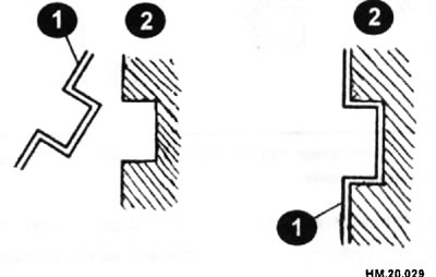
1 - brake shoe retainer; 2 — brake caliper.
Install the mounting bolt:
♦ front brake - lower guide pin and tighten it to a torque of 22-31 N·m;
♦ rear brake - upper guide pin and tighten it to a torque of 38-48 Nm.
- Check if the brakes are "grabbing".
- Install the wheels on the car.
Brake caliper
Removal
- Remove the wheels from the car.
- Drain the brake fluid.
- Disconnect the brake hose from the brake mechanism. Cap the end of the pipe to prevent any remaining liquid from leaking out of the pipe.
- Remove the connecting hollow bolts and the brake caliper mounting bolts and remove the caliper by rotating it upwards so that it clears the brake disc.
- Remove the brake disc (if necessary). Brake pads may remain on the caliper.
Installation
- Install the brake disc (if it was filmed).
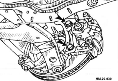
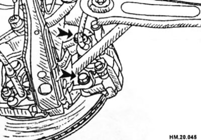
- Install the brake caliper on the vehicle and tighten the mounting bolts (arrows) to the following torque: front brake - 137.0-176.0 N·m, rear brake - 71.6-97.0 N·m
Front brake
Rear brake
- Before installing the caliper on the steering knuckle, wipe off any oil from the steering knuckle axle washers and the caliper mounting surfaces.
- Install the brake hose to the caliper and tighten the connecting bolt to a torque of 16.7-19.6 N·m.
Caution: Copper sealing washers for connecting bolts cannot be reused.
- Connect the brake hose to the brake hose installation tab.
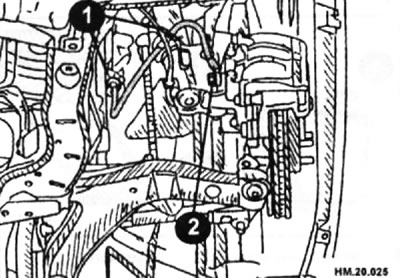
1 - fixing plate; 2 - connecting bolt.
Caution: Fill the reservoir with fresh DOT3 brake fluid. Drained brake fluid cannot be reused.
- Bleed the brakes.
- Install the wheels on the car.
Disassembly
- Clean the outer surface of the brake mechanism with a special cleaner or alcohol.
Caution: Do not use gasoline, kerosene or solvents containing them.
- Remove the guide pin mounting bolts from the brake caliper, then the brake pads, noise-absorbing linings and brake pad retainers.
- When removing the brake shoe retainer (2) from the brake caliper (1), lift the brake shoe retainer in the direction shown by arrow (A) in the figure, otherwise it may become deformed.
- Remove the guide pins and guide pin boots from the brake caliper.
- To remove the piston and piston boot, insert a wooden block or rag as a cushion as shown in the figure, place the piston on the workbench and apply compressed air to the hole for installing the connecting hollow bolt and push the piston out.
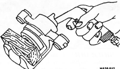
- The air pressure should not exceed that required to slowly extract the piston. If the piston is pulled out with too much force, it may be damaged.
Caution: Do not place your fingers under the piston as this may cause serious injury.
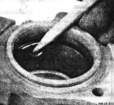
- Using a flat-blade screwdriver, remove the piston seal from the groove in the cylinder body. It is better to use a plastic or wooden tool. A pencil works well for this purpose.
Caution: Be careful not to damage the cylinder bore walls.
Checking the caliper
- Wash all parts with a special cleaner or alcohol, then dry with compressed air. The air must pass through the filter and be dry.
Cylinder
- The inner surface of the cylinder should be free of scratches, corrosion and signs of wear. If there is severe damage, replace the caliper.
- Minor damage from corrosion and foreign objects can be removed with fine-grained sandpaper.
Brake caliper
- Check the bracket for wear, cracks, or other damage. If damage or deformation is detected, the damaged part must be replaced.
- Replace the piston if it is scratched, corroded, worn or damaged.
Caution: The piston sliding surface is galvanized and should not be ground even if corrosion or foreign particles are present.
Guide pins with mounting bolts and protective covers
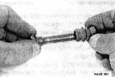
- The specified parts are subject to replacement if there is wear, corrosion, cracks or other damage.
Assembly
Caution: When assembling, use NISSAN genuine rubber lubricant (KRE00 00010. KRE 00010 01).
- Wet the cylinder body with clean brake fluid.
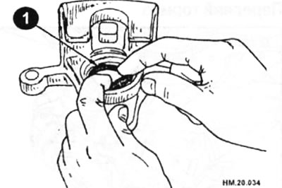
- Apply rubber grease to the new piston seal (1) and insert the seal into the groove on the cylinder body.
- Apply brake fluid or rubber lubricant to the new rubber boot, place the boot on the piston, and insert the edge of the piston boot that is installed on the cylinder into the groove on the brake cylinder body.
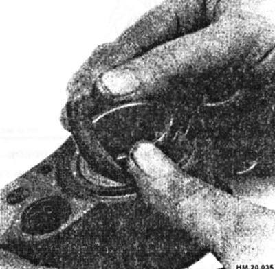
- Insert the piston boot lip that fits onto the piston into the groove on the piston.
Caution: Press the piston evenly and vary the pressing force so as not to damage the inner walls of the cylinder bore.
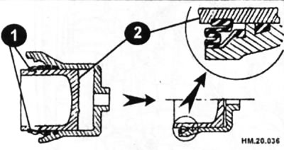
1 — piston cover; 2 — piston.
- Secure the piston boot with a new retaining ring.
Caution: Make sure the boot fits snugly into the groove on the cylinder body.
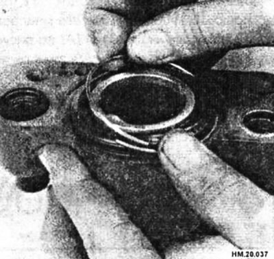
- Install the guide pin retaining bolt and guide pin boot onto the brake caliper.
- Apply silicone grease to the back sides of the brake pads and both sides of the noise-absorbing pads, and attach the inner pads to the inner brake pad and the outer pads to the outer brake pad.
- After installing the noise-absorbing pads on the brake pads, install them on the brake caliper.
- Install the brake shoe retainer onto the brake caliper.
Caution: When installing the brake shoe retainer, install it tightly and so that it is not located above the brake caliper (see picture).
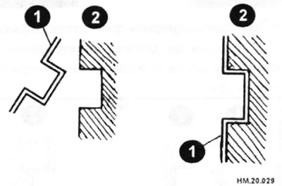
1 - brake shoe retainer; 2 — brake caliper.
[The publication is reprinted from this resource www.NISSANBOOK.ru]
- Install the cylinder body. Tighten the guide pin mounting bolt to a torque of: 22-31 N·m for the front brake; 38-48 Nm - for the rear brake.
Checking the brake disc
Beating
- Secure the disc to the wheel hub with at least two nuts.
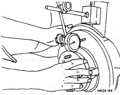
- Measure the axial runout of the disc using a dial indicator. First, make sure that the axial clearance in the hub bearing is within the permissible limits. Maximum permissible runout 0.04 mm - for the front brake; 0.05 mm - for the rear brake.
- If the runout exceeds the specified value, try adjusting the position of the disc on the hub by successively moving it one hole at a time.
- If the rearrangement does not produce the desired result, regrind the disc.
- It is recommended to treat the disc surface regardless of the dial indicator readings, since after treatment the disc surface will be smooth and completely flat, which will eliminate brake pedal pulsation or other symptoms associated with an untreated disc. If you decide not to have the disc surface treated in a machine shop, at least sand the disc surface using circular motions with sandpaper.
- The disc can only be processed to a minimum thickness. The minimum wear thickness is imprinted on the inside of the disc. The thickness of the disc can be checked using a micrometer.
Thickness
- Measure the thickness of the disc with a micrometer at 8 points around the circumference.
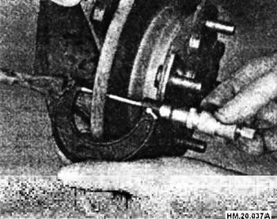
The scatter of measurement results should not exceed 0.015 mm, otherwise the disk must be replaced.
- Front brake:
♦ maximum permissible disk thickness - 26.0 mm:
♦ nominal thickness - 28.0 mm.
- Rear brake:
♦ maximum permissible disk thickness - 14.0 mm:
♦ nominal disc thickness - 16.0 mm.
Brake bedding-in
After resurfacing or replacing brake discs, after replacing brake pads, or if the brake pedal feels soft after a short period of mileage, bed in the contact surfaces of the brake pads in accordance with the procedure described below.
Caution: This operation should only be performed on a road with light traffic. Be very careful when breaking in your brakes.
- On a level road, accelerate the car to a speed of 50 km/h.
- Using moderate pressure on the brake pedal, stop the car from a speed of 50 km/h. Adjust the pedal pressure so that the car stops in 3-5 seconds.
- To cool the brake system components, drive the vehicle without stopping at a speed of 50 km/h for at least 1 minute.
- To fully break in the brakes, repeat the steps described above at least 10 times.