


Parking brake control installation elements
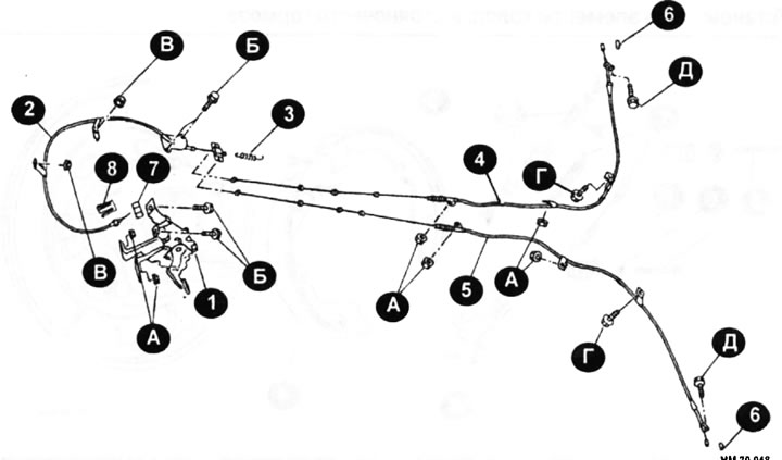
1 — pedal bracket assembly; 2 - front cable; 3 - return spring; 4 - right rear cable; 5 - left rear cable; 6 - pin; 7 - adjusting nut; 8 — spring cap; A, B - fastening nuts; B, G, D — fastening bolts.
Cables
Cables need to be replaced when they require frequent adjustment to compensate for the increased length of the cable due to stretching. Typically, the parking brake system should be adjusted no more than once a year, however, if adjustment is required monthly, the cable should be replaced.
Removal
- Raise the vehicle and support it securely.
- Remove both rear wheels.
- Remove the front door sill plate on the driver's side.
- Remove the front body side trim from the driver's side.
- Remove the lower portion of the front panel on the driver's side.
- Remove the driver's side dash panel trim.
- Remove the left side fan.
- Remove the relay box stand mounting screw.
- Disconnect the parking brake indicator switch connector.
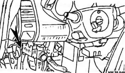
- Remove the adjusting nut indicated by the arrow in the figure.
- Loosen the pedal bracket mounting bolts and nuts and remove the pedal bracket assembly.
- Remove the center console.
- Remove the front cable mounting bolts and nuts and remove the front cable from the vehicle.
- Remove the center muffler.
- All-wheel drive models: Remove the driveshaft.
- Remove the left wheel caliper and hang it aside. Be careful not to pinch the hoses and tubes.
- Remove the brake disc. Do not remove the hub.
- Perform the previous two operations on the right wheel.
- Remove the rear cable from the crank arm.
- Remove the bolts and nuts securing the right and left rear cables and remove the right and left rear cables.
Installation
- Installation is carried out in the reverse order of removal, taking into account the following.
Caution: The adjusting nut cannot be reused.
- Install a new cable through the rubber grommet in the floor. Make sure the rubber bushing is seated correctly.
- Always install only a new adjusting nut.
- When connecting the cables, apply a thin layer of heat-resistant graphite grease to the mounting nuts.
- Tighten nuts A and bolts B to a torque of 10.8-14.6 N·m; fastening bolts B with a torque of 8.3-11.3 N·m; fastening bolts G with a torque of 17.5-23.7 N·m, fastening bolts D with a torque of 21-28.2 N·m.
- Adjust the parking brake.
Parking brake shoes
Parking brake shoe mounting elements
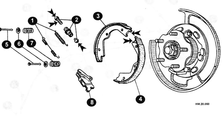
1 - return spring; 2 — regulator assembly; 3 — shoe (driven); 4 — shoe (leading); 5 - anti-chatter pin; 6 — holder; 7 - anti-chatter spring; 8 — crank lever.
Removal
- Raise and securely support the vehicle.
- Remove the rear wheel you are going to work on.
Caution: Clean the brake disc and back plate from dust using a vacuum cleaner. Do not blow out dust with compressed air!
- Remove the brake disc while the parking brake pedal is in the fully released position.
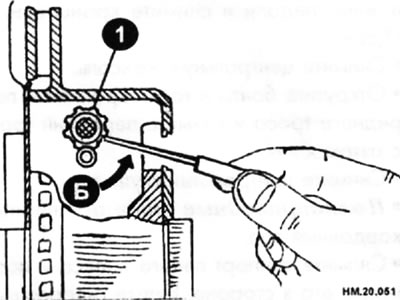
- If the brake disc cannot be removed immediately, secure the brake disc using the wheel nuts and remove the plug from the disc. Move the brake pads together and release the disc using a screwdriver by turning the adjuster wheel (1) in direction B, and then remove the disc.
- Using special brake spring pliers, remove one tension spring from the brake pads.
- If you don't have pliers, you can use a simple device made yourself from steel wire with a diameter of 1.5-2.0 mm.
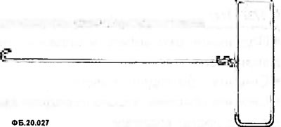
- Remove the pads from the vehicle, marking their location and the position of the adjuster.
Examination
- Check the thickness of the working layer of the brake pads.
♦ Standard thickness: 3.2 mm.
♦ Maximum permissible thickness: 1.5 mm.
- Determine the inner diameter of the brake drum.
♦ Standard value of internal diameter: 190 mm.
♦ Maximum permissible value of internal diameter: 191 mm.
- Inspect the brake drum surface that contacts the shoes for excessive wear or damage.
- Check the anti-chatter pin for wear and corrosion.
- Check the return spring for weakness.
- Check if the regulator moves smoothly.
- Inspect visually and with a caliper for excessive wear, cracks, or damage inside the brake drum.
Installation
Installation is carried out in the reverse order of removal, taking into account the following.
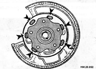
- Apply RBC brake lubricant during assembly (Poly Butyl Cuprysil) or silicone grease in the places shown in the figure with the arrows depicting the parking brake parts.
- Apply the same grease to the brake wheel shield in the places indicated by arrows in the figure.
- There is a difference in the orientation of the adjusters between the left and right wheel brake mechanisms. Assemble the regulator so that its threaded portion extends when the regulator is rotated in the direction shown by the arrow.
[Original publication on the portal: www.NISSANBOOK.ru]
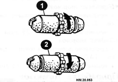
1 - right wheel brake mechanism; 2 — left wheel brake mechanism.
- Turn the regulator to shorten it.
- When assembling the regulator, apply RVS lubricant to its threads (Poly Butyl Cuprysil) or silicone grease.
- Adjust the parking brake pedal travel.
- After replacing brake pads, brake discs, or if the brakes are not working properly, perform brake bedding.
- The brake bedding operation is performed on a moving vehicle. The driving mode should be as follows:
♦ The car is moving forward.
♦ The speed of the car should be approximately 40 km/h.
♦ The force applied to the parking brake pedal should be approximately 147 N (15 kg).
♦ Braking should be done at a distance of approximately 100 m.
- After the brake bedding operation, check the travel of the parking brake pedal. If the stroke size (number of clicks) differs from the standard value (see chapter "Control dimensions and adjustment data of the vehicle"), repeat the adjustment.
- To prevent excessive heat buildup on the brake pads, allow the brakes to cool for approximately 5 minutes after each bedding stage. Avoid bedding too vigorously, as this may cause uneven or premature wear of the brake pad linings.