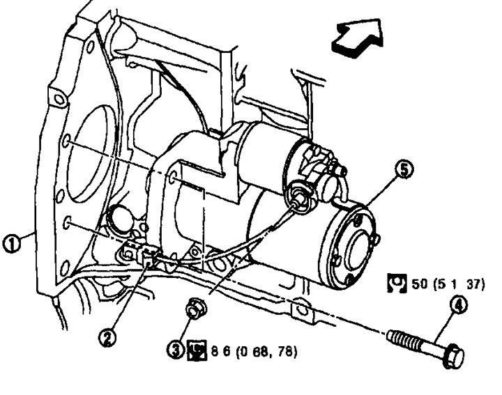
Removal. 1. Cylinder block; 2. Connector "S"; 3. Terminal "B" nut; 4. Starter mounting bolt; 5. Starter;
 In front of the car.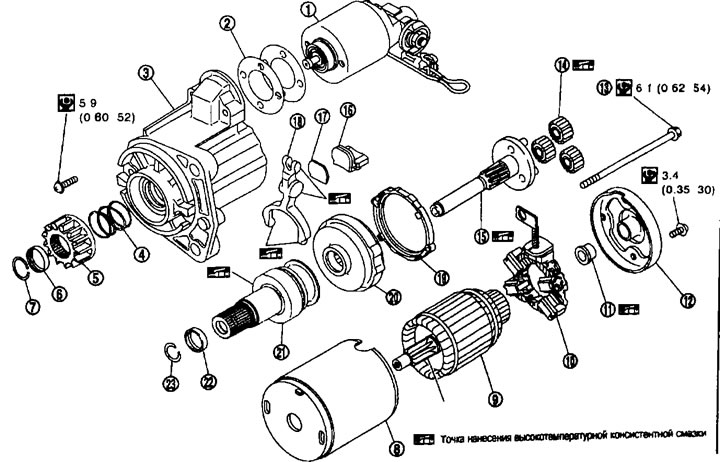
Disassembly. Type-M000TA0271. 1. Magnetic switch assembly; 2. Adjusting washer; 3. Gear housing; 4. Spring; 5. Gear; 6. Gear limiter; 7. Limiter clamp; 8. Stator; 9. Rotor; 10. Brush holder assembly; 11. Rear metal; 12. Back cover; 13. Through bolt; 14. Planetary gear; 15. Pinion shaft; 16. Stuffing; 17. Plate; 18. Shift lever; 19. Stuffing; 20. Internal gear; 21. Freewheel clutch; 22. Retaining ring; 23. Retaining ring.
Removal and installation
Removal
1. Disconnect the cable from the negative battery terminal.
2. Remove the front exhaust pipe. See chapter "Accelerator, fuel system and exhaust system".
3. Unscrew the nut of terminal "B" (A) and disconnect the wiring of terminal "B".
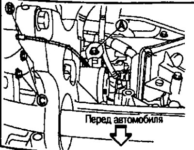
4. Disconnect the "S" (B) connector.
5. Loosen the starter mounting bolts (C).
6. Remove the starter from the vehicle in an upward direction.
Installation
Installation is performed in the reverse order of removal.
Caution: Tighten the terminal "B" nut with care.
Disassembly and assembly
Assembly
When assembling the starter, apply high temperature grease to the bearing, gears and friction surfaces.
Please strictly follow these instructions:
Adjusting the starter pinion protrusion
Bias
- Compare the offset "L" in the height of the starter gear when it is pressed back when the electromagnetic switch contacts are closed and when it is pressed back by hand until it touches the limiter.
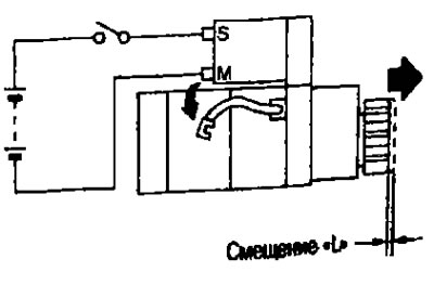
Offset "L": See below p. "Technical data and specifications".
- If the offset is different from the norm, adjust using the adjusting washer.
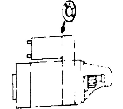
Examination
Checking the electromagnetic switch
- Before you begin testing, disconnect the cable from the negative battery terminal.
- Disconnect the starter terminal "M".
1. Checking the conductivity [between terminal "S" (A) and the switch body].
![1. Checking the conductivity [between terminal «S» (A) and the switch body].](https://www.nissanbook.ru/img/x-trail/1566.jpg)
- If there is no conductivity, replace the electromagnetic switch.
2. Checking the conductivity [between terminals "S" (A) and "M" (C)].
![2. Checking the conductivity [between terminals «S» (A) and «M» (C)].](https://www.nissanbook.ru/img/x-trail/1567.jpg)
- If there is no conductivity, replace the electromagnetic switch.
Checking the gear/clutch
1. Check the gear teeth.
- Replace the gear if the teeth are worn or damaged (Also check the condition of the ring gear teeth).
2. Check the gear teeth (if any).
- Replace the gearbox if the teeth are worn or damaged. (Also check the condition of the gear teeth on the rotor shaft).
3. Make sure the starter pinion locks in one direction and rotates freely in the opposite direction.
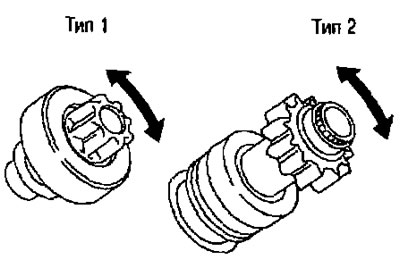
- If it locks up or rotates in both directions or feels unusually resistant, replace.
Checking the brushes
- Check if the brushes are worn out.
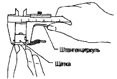
Minimum brush length: See below. "Technical data and specifications".
- If the measured value is less than the norm, replace the brushes.
Checking springs and brushes
- Check the brush spring pressure by separating the spring from the brush.
Spring pressure (with a new brush): See below p. "Technical data and specifications".
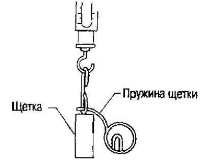
- If the measured value is less than the norm, replace the brush springs.
Checking the brush holder
1. Perform an insulation test between the brush holder (+) and its base (-).
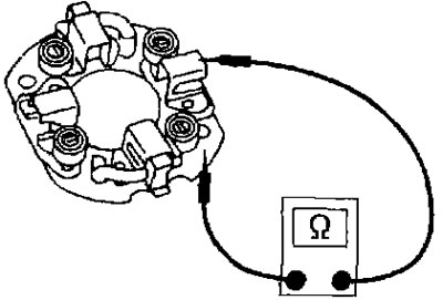
- If there is no conductivity, replace the brush holder.
2. Check if the brush moves freely.
- If the brush holder is bent, replace it; if the sliding surface is dirty, clean it.
Stator check
- The magnet is attached to the stator with glue. Check if the magnet is attached to the stator and if there are any cracks. Replace the faulty components in the kit.
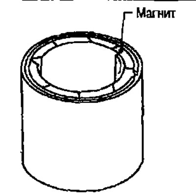
Caution: Do not clamp the stator in a vice or hit it with a hammer.
1. Conductivity test (between two adjacent segments).
- If there is no conductivity, replace the rotor assembly.
2. Insulation testing (between the commutator lamellas and the shaft).
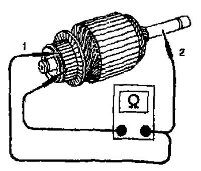
- If there is conductivity, replace the rotor assembly.
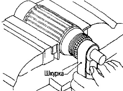
3. Check the surface of the switch.
- If the surface is rough, lightly sand it with #500-600 sandpaper.
4. Check the commutator diameter.
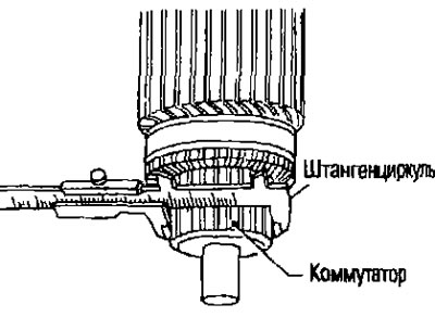
Minimum commutator diameter: See below. "Technical data and specifications".
The original can be read on the website: nissanbook
- If the measured value is less than the norm, replace the rotor assembly.
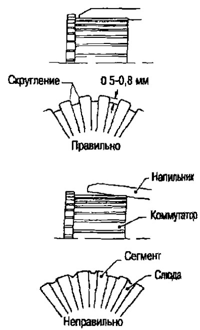
5. Check the depth of the insulating mica from the surface of the commutator.
- If it is less than 0.2 mm, trim it to 0.5-0.8 mm.