


2. Remove the glove compartment lid and front panel (see Chapter 33 of this Section).
3. Disconnect the fan motor wiring and rubber tube (see photo).
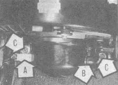
41.3. Fan motor wiring connector plug (A), rubber tube (B), intake box mounting bolts (C)
4. Remove the mounting bolts and remove the motor and fan from the intake box base (see photos).
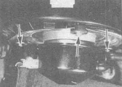
41.4A. Fan Motor Mounting Bolts (marked with arrows)
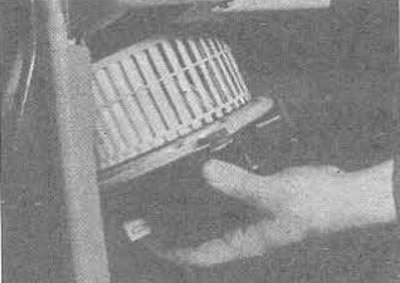
41.4B. Removing the fan motor and fan from the intake box
5. Remove the coating (see photo).
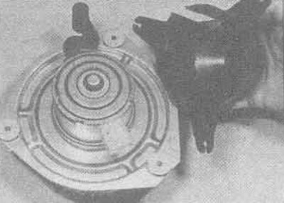
41.5. Removing the protective coating of the fan motor
6. If necessary, by unscrewing the nut, the fan can be removed from the electric motor shaft (see photo). The fan motor resistor is installed in the connecting pipe of the heating device (see photo 39.7).
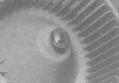
41.6. Heater Fan Lock Nut
7. The intake manifold can be removed by unscrewing the bolts from the mounting brackets.
8. Assembly is carried out in reverse order.