


Table of contents: Removal and installation ↓ Adjustment ↓
Removal and installation
1. Disconnect the negative battery cable.
2. Remove the four screws and remove the lower panel from the steering column.
3. Remove the ashtray and radio/heater trim (see Chapter 37 of this Section, Item 7).
4. Remove the glove compartment lid and front panel as described in Chapter 33 of this Section.
5. Carefully remove the buttons from the heater control levers (see photo).
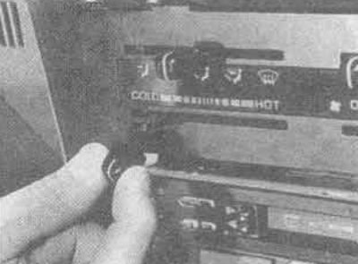
39.5. Removing the heater control lever
6. Remove the two mounting screws and remove the heater control faceplate (see photos).
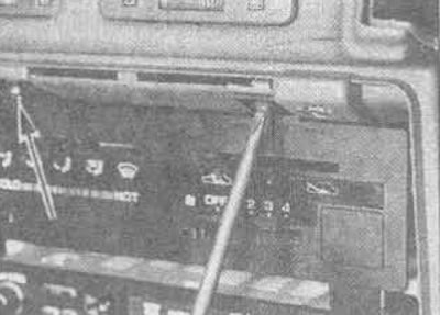
39.6A. Removing the heater faceplate screws (the other one is marked with an arrow)...
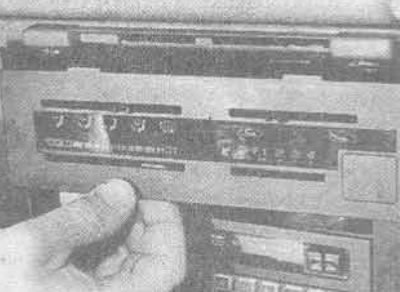
39.6V.... removing the front panel
7. Disconnect the control cables from the heater and intake manifold by releasing the outer cable clamps and disconnecting the inner cable ends from the ends of the control lever (see photo).
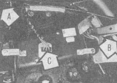
39.7. Air intake control lever cable (A), temperature control lever cable (B), heater fan resistor (C)
8. Remove the screws securing the edges and pull out the heater control panel (see photos), until the fan switch wires can be disconnected. Remove the cables, noting their orientation.
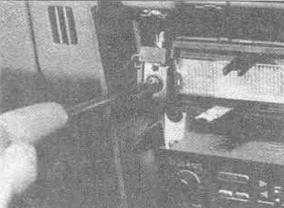
39.8A. Remove the mounting screws at the edges...
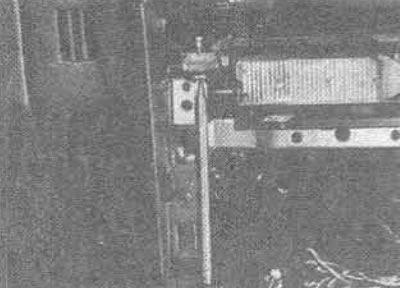
39.8V.... to remove the heater panel assembly
9. To disconnect the cables from the control panel, remove the brackets and pull them out of the brackets (see photo).
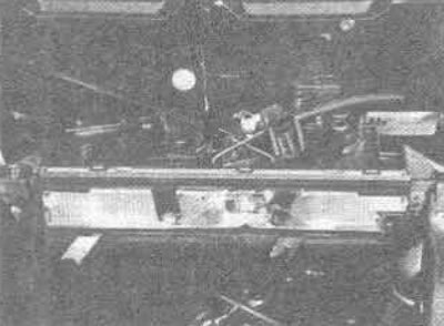
39.9. The control cables are attached to the heating device with metal brackets
10. Assembly is carried out in reverse order.
Adjustment
11. First remove the lower part of the dashboard and parts of the glove box as described above. Note that access is extremely limited and it would be useful to have a small mirror and a good light. Using the seat position adjusters, move the front seats all the way back.
12. To adjust the fan and heater flap rods on the right side of the heater, first disconnect the air regulator cable from the side rod (see point 7 above).
As shown in Figure 11.27, disconnect the throttle rods to the rear of the side rod, push both throttle arms all the way down, and turn the side rod fully counterclockwise. Hold the arms and side rods in this position until the rods are replaced; first the lower pull, then the upper.
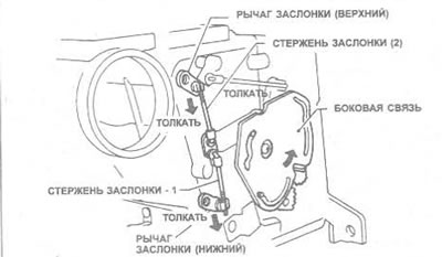
Figure 11.27. Adjusting the fan damper control rod
14. As shown in Figure 11.28, disconnect the heater flap rod above the side rod, push the flap lever forward and turn the side rod clockwise until it stops. Hold the lever and rod in this position while the rods are being replaced.
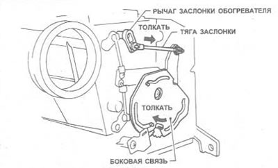
Figure 11.28. Adjusting the heater flap control rod
15. Connect the air regulator lever cable to the side rod. Move the regulator lever to the position as shown in Figure 11.29, turn the side rod clockwise until it stops, and then pull out the cable, remove any play before attaching it to the bracket.
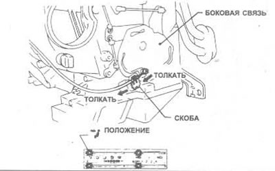
Figure 11.29. Adjusting the air flow control lever cable
16. To regulate the temperature, first disconnect the cable from the air damper rod on the left side of the heater (see point 7 above).
17. As shown in Figure 11.30, disconnect the rod (1) from the air flow flap lever. Turn the air flow flap control lever as far as it will go in the direction shown and pull the rod until its end engages with the rod (2); at this point the spring should be compressed by 2 mm. Reconnect the control rod (1) to the air damper regulator lever.
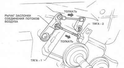
Figure 11.30. Water flow control adjustment
18. Connect the temperature regulator lever cable to the air damper lever, move the temperature regulator lever to maximum "Hot" and turn the air damper lever as far as it will go, in the direction shown in Figure 11.31. Remove the cable insulation to eliminate play before securing it.
(Read more on the website: nissanbook)
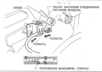
Figure 11.31. Adjusting the temperature control lever cable
19. To adjust the air flow control lever cable, turn the lever to the "repeat" position, squeeze it as shown in Figure 11.32, then remove the cable insulation to remove any play before securing it (see photo).
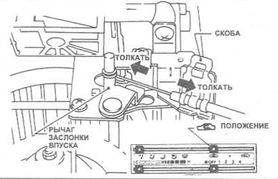
Figure 11.32. Adjusting the air intake lever control cable
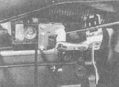
39.19. End of the air intake control lever cable in the intake box
20. Finally, check that all controls operate correctly before installing the heater faceplate and knobs, glove box components, radio/heater and ashtray trim, and lower instrument panel.