


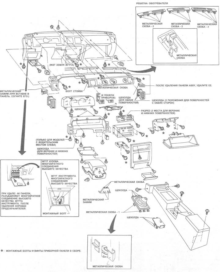
Figure 11.25. Exploded view of the instrument panel - the version with the driver's seat on the left is shown
1. Disconnect the negative battery cable.
2. Pull out the tilt lock lever and pull the steering column down until it stops, then remove the lower instrument panel and steering column covers as described in Section 10, Chapter 21, Items 2 through 4 (see photo).
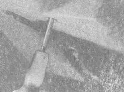
37.2. Removing the steering column cover mounting screw
3. Remove the steering wheel and remove the steering column lock switches.
4. Remove the instrument panel (see Section 12) and pull out the speedometer drive cable.
5. Remove the glove compartment lid and front panel (see Chapter 33 of this Section).
6. Unscrew the bolt (but don't delete it completely) hood release lever (see Chapter 9 of this Section, Items 3 and 4).
7. Remove the ashtray and remove the four screws (one at the base on each side and two on top), that secure the radio/heater trim. Remove the trim (see photos).
Source is available on the resource nissanbook.ru
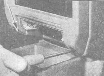
37.7A Radio/Heat Trim Panel Base Screws (the other one is shown by the arrow)...
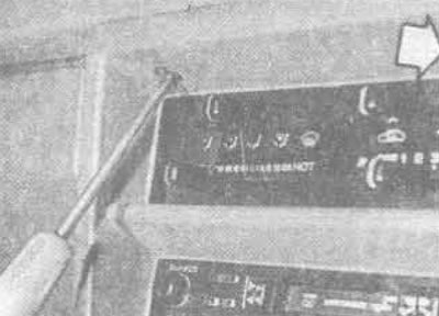
37.7V.... and the top screws (the other one is shown by the arrow)
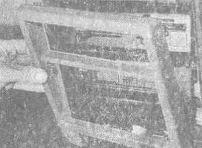
37.7C. Removing radio/heater trim
8. Remove the radio (see Section 12).
9. Remove the heater control knobs and pull out the heater control panel as described in Chapter 39 of this Section, then remove the four screws (two on each side) securing the heater panel assembly.
10. Remove the three screws securing the ashtray mounting panel, remove it and disconnect the ashtray light bulb (see photos).
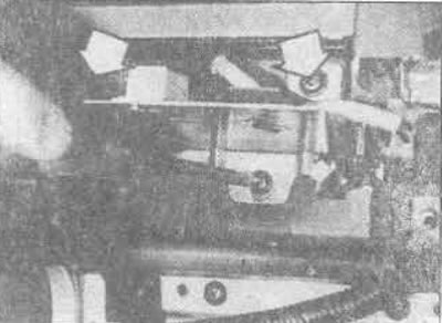
37.10A. Ashtray mounting panel screws (the top two are marked with arrows)
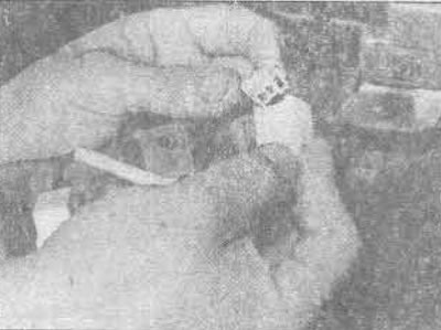
37.10B. Disconnecting the ashtray light bulb
11. Unscrew the bolts from the hangers that secure the edges of the dashboard to the car body (see photo).
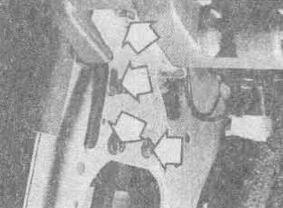
37.11. The panel is secured with a hanger on each side
12. Carefully remove the three heater grilles along the front edge of the instrument panel surface and remove the screws securing it to the bulkhead (see photos).
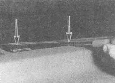
37.12A. Remove the heater grilles at the points as shown...
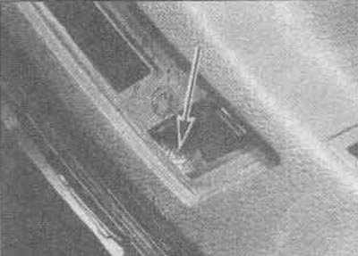
37.12V....to gain access to the panel mounting bolts
13. Remove and disconnect all switches installed in the instrument panel (see Section 12).
14. Remove the fuse panel cover, unscrew the mounting bolts and slide it to the side. Unscrew the SMJ mounting bolts (Multiple Connection of the Highest Quality).
15. Carefully remove the instrument panel from the bulkhead, disconnecting any electrical connections.
16 Remove the instrument panel.
17 The upper protective panel can be removed from the main instrument panel if required by unscrewing the retaining nuts and bolts.
18 Assembly is carried out in the reverse order. Refer, where necessary, to the Chapters of this Section and Sections 10 and 12.