Dashboard design
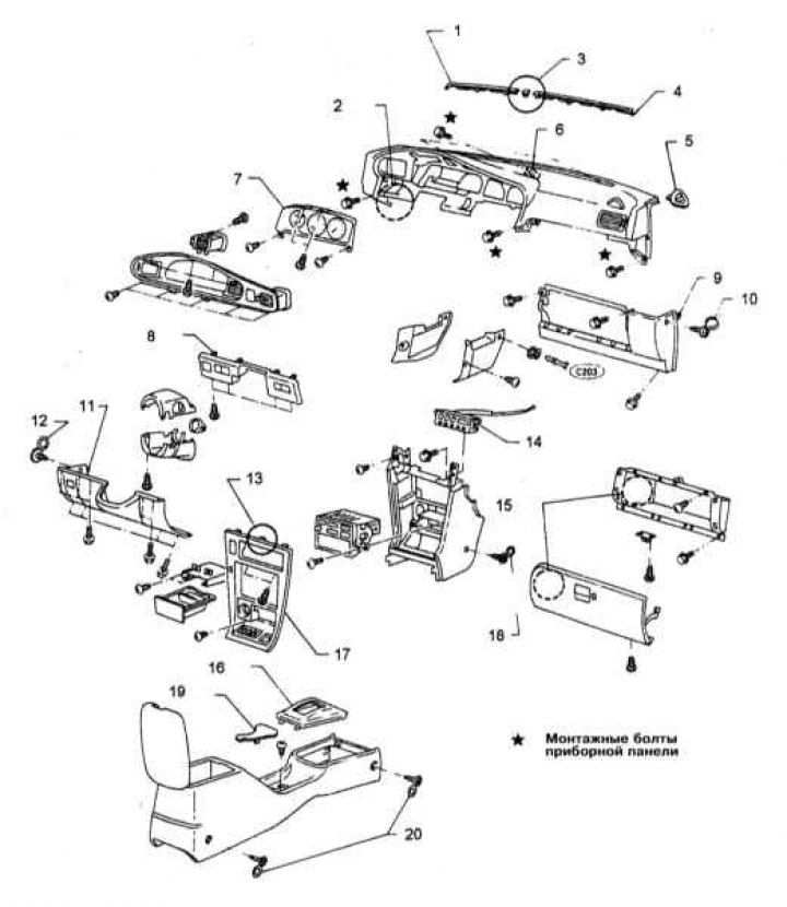
1 - Windshield blower deflector; 2 - Docking station; 3 - Remote insert; 4 - Deflector fastening lock; 5 - Retainer; 6 - O-ring; 7 - Instrument cluster; 8 - Retainer; 9 - Retainer; 10 - Decorative cover of the fixing screw; 11 - Retainer; 12 - Decorative cover of the fixing screw; 13 - Mounting bracket; 14 - Control panel for the operation of the heater and A/C; 15 - Glove box; 16 - Facing of the shift lever; 17 - Facing lining; 18 - Decorative cover of the fixing screw; 19 - Overlay; 20 - Decorative cover of the fixing screw
Warning! The car models covered in this manual are equipped with an additional security system (SRS). Before doing any work near the airbag unit, steering column or instrument panel, turn off the SRS to avoid injury if it is accidentally deployed (see chapter Onboard electrical equipment). SRS circuit wiring is easily identified by the yellow color of the insulation.
The design of the instrument panel is shown in the illustration.
Disconnect the negative cable from the battery.
Attention! If the stereo system installed in the car is equipped with a security code, before disconnecting the battery, make sure that you have the correct combination to activate the audio system!
Instrument panel trim
1. Remove the steering column covers (see Section Removal and installation of sections of a casing of a steering column).
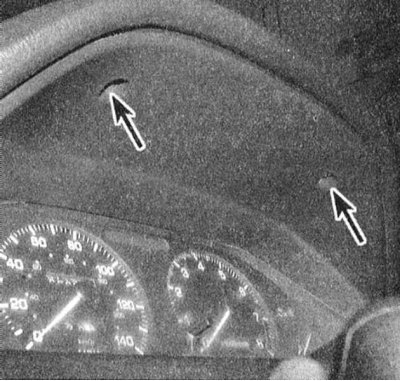
2. Turn out two fixing screws in the top part of facing of an instrument panel. Gently prying with a screwdriver wrapped with tape, release the latches and separate the lower part of the shield lining from the instrument panel.
Note. On models equipped with a speed control or anti-theft system, appropriate switches are mounted in the fascia, from which the electrical wiring must be disconnected at the last stage of removing the panel.
3. Installation is carried out in the reverse order. Track reliability of a latching of clamps.
Knee support
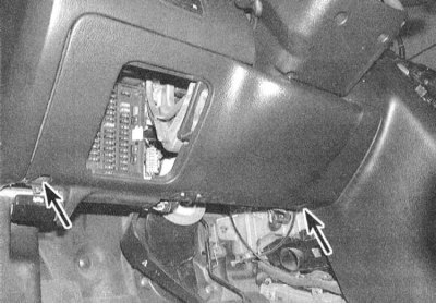
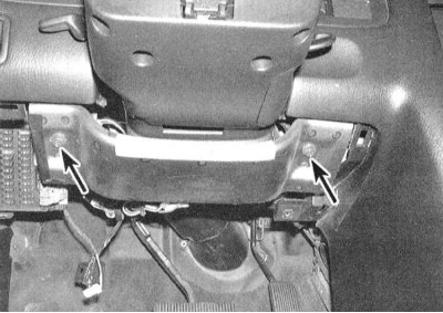
1. Remove the cover from the cabin fuse box, then remove the two screws located on the bottom edge of the knee brace panel. Remove the thrust assembly.
2. If the stop is removed in order to provide access to other components, it is enough to unscrew the fasteners and lower the panel.
3. Installation is carried out in the reverse order.
Center trim section
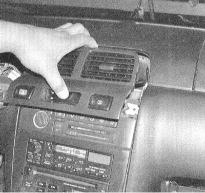
1. Using a tape-wrapped screwdriver, remove the center trim section from the vehicle's instrument panel.
2. After separating the panel, disconnect the electrical wiring from the switches built into it (see chapter Onboard electrical equipment).
3. Installation is carried out in the reverse order.
Glove box
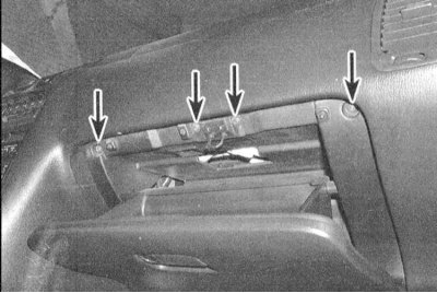
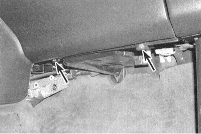
1. Open the glove box and remove the four top and two bottom screws securing the assembly. Remove the glove box cover from the instrument panel.
 |  |
2. Installation is carried out in the reverse order.