
Instrument cluster
The instrument cluster of the vehicle dashboard includes a set of main meters, control lamps and light indicators.
Speedometer, odometer and mileage counter of the current trip
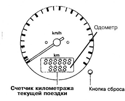
The speedometer indicates the vehicle's speed in km/h. below the axis of the indicator arrow is a digital display, the upper field of which is reserved for the odometer readings (total car odometer), lower - under the readings of the mileage counter of the current trip.
Tachometer
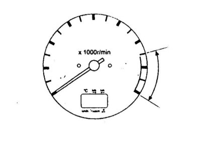
Next to the dial of the speedometer is an engine speed indicator - a tachometer. The meter needle shows the driver the engine speed in rpm. Make sure that the engine speed does not rise so much that the pointer needle enters the range of the meter scale highlighted in red.
Coolant temperature meter
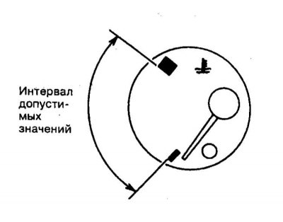
The meter records the temperature of the engine coolant. Meter readings may vary depending on ambient temperature and driving conditions. If the instrument pointer goes beyond the range of permissible scale values, you should immediately stop moving and let the engine cool down. Prolonged operation of an overheated engine can lead to its failure.
Fuel consumption meter
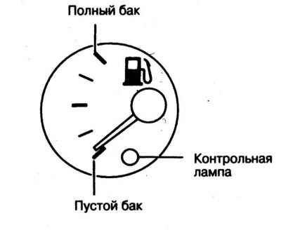
The fuel consumption meter indicates the current level of fuel in the tank. When braking, accelerating, maneuvering and driving the vehicle on an inclined plane, the meter readings may vary slightly. The connection diagram of the meter is such that it continues to give a working value even when the ignition is off. When the fuel level in the tank drops to a critical value, the control lamp built into the dial of the meter is activated.
Pilot lamps and signal buzzers
A whole range of warning lamps is built into the assembly of the car's instrument cluster, with the help of which the driver receives important information about the serviceability / violation of the functioning of the main units and systems of the car. Below, the reader is offered information on the principle of operation of each of the provided light indicators separately.
Designations of control lamps and light indicators
| Designation of a control lamp | The purpose of the control lamp, (color) |
| AIR BAG | Airbag warning lamp (SRS) (red) |
 | Brake fluid level warning lamp (red) |
 | charge control lamp (red) |
| Control lamp of loose closing of doors (red) | |
| Oil pressure warning lamp (red) | |
 | Control lamp of a cocking of a parking brake (red) |
 | Minimum fuel warning lamp (yellow) |
 | ABS warning lamp (orange) |
| Control lamp for low fluid level in the washer reservoir (orange) | |
| Control lamp of a condition of work of the engine (orange) | |
| O/D OFF | Overdrive Disable Indicator (orange) |
 | Rear fog light indicator (orange) |
| High beam indicator (blue) | |
| CRUISE | Tempostat control lamp (green) |
| Turn signal indicator light (green) |
Lamp health check
1. Set the parking brake and turn on the ignition (do not start the engine), - indicator lamps for charge, oil pressure and engine status should light up on the instrument panel
Also, the ABS and SRS warning lamps should turn on briefly and soon go out
AIR BAG
2. If any of the listed lamps does not work, then it is out of order, or there is an open circuit in its electrical wiring. Try to identify and eliminate the cause of the failure.
Control lamp of a charge of the rechargeable battery

The charge control lamp should light up when the ignition is switched on and go out immediately after starting the engine. The inclusion of this warning lamp with the engine running warns the driver about a malfunction in the charging system, i.e., the battery goes into discharge mode. You should immediately turn off all consumers of electricity, the operation of which does not affect road safety and try not to stop the engine, as an attempt to restart it can lead to the final discharge of the battery. The vehicle should be immediately driven to the nearest service station to diagnose the failure and perform the necessary remedial repairs.
Engine oil pressure warning lamp
The engine oil pressure warning lamp should come on when the ignition is turned on and go out immediately after starting the engine. The flashing of the lamp with the engine running indicates a pulsating decrease in the working pressure of the engine oil in the engine. When the light stays on, it indicates that the oil pressure has dropped to a dangerously low level, which is fraught with serious internal engine damage, up to and including its complete failure. In both cases, urgent action should be taken to correct the oil level, identify and eliminate the causes of pressure drop.
Engine status warning lamp
The control lamp lights up briefly when the ignition is switched on. Its operation at any other time indicates a possible malfunction of one of the electrical systems of the power unit. In the absence of visible signs of failures in the functioning of the systems of the power unit and a decrease in the dynamics of the vehicle, violations fixed by the inclusion of a warning lamp can cause an increase in fuel consumption or an increase in the toxicity of emissions. Ignoring the signals of the warning lamp is fraught with serious engine damage, up to the failure of the unit. If the warning lamp comes on while driving, immediately stop driving, park in a safe place and turn off the engine, then, after a short time, start, while observing the behavior of the warning lamp. If the lamp does not return to normal operation and remains on, the vehicle should be driven to the nearest service station for detailed diagnosis and necessary remedial repairs. Until the malfunction of the engine systems is eliminated, try to move at a moderate speed, avoiding sudden accelerations with full depressing of the gas pedal.
Note. Even if the indicator lamp returns to normal when the engine is restarted (i.e., goes out), you should seek advice from a workshop as soon as possible, especially if this kind of indicator light does not occur for the first time.
Continued operation of the vehicle with the check engine light on may result in premature failure of the catalytic converter. Remember that failures and damages resulting from the operation of the car with the control lamp on are not covered by the manufacturer's warranty obligations! In addition to the functions described above, on equipped models, this warning lamp also functions as a NATS V2.0 warning lamp.
Control lamp of inclusion of a high beam
This indicator light comes on when the vehicle's high beam headlights are switched on (see below).
Control lamp of inclusion of back foggy lanterns
This indicator light confirms that the rear fog lights are working properly when they are turned on.
Brake fluid level warning lamp
The operation of this warning lamp informs the driver of a critical decrease in the level of hydraulic fluid in the brake system.
Control lamp of a cocking of a parking brake

This warning lamp illuminates continuously when the parking brake is applied, reminding the driver to release it before driving off. Driving with the parking brake applied leads to rapid overheating and failure of the brake mechanisms of the rear wheels of the car and premature wear of the rear wheel tire treads, and, in addition, may cause a malfunction of the anti-lock brake system (ABS) (see below). One of the possible reasons for the gradual decrease in the level of brake fluid is the normal wear of the friction linings of the brake pads. When the warning lamp comes on, the car should be driven to the nearest service station to assess the condition of the pads and check the tightness of the hydraulic path of the brake system.
A short-term operation of the control lamp also occurs when the ignition is switched on (even with the parking brake released).
ABS warning lamp

With the appropriate vehicle equipment, this warning lamp lights up when the ignition is turned on and goes out immediately after the engine is started, thereby confirming the correct operation of the anti-lock brake circuit. The operation of the warning lamp in any other situations indicates that the self-diagnosis system has detected violations in the ABS circuit. The vehicle should be immediately driven to the nearest service station for a detailed diagnosis of the system and the necessary remedial repairs.
Note. When the warning light comes on, the anti-lock brake system is disabled, but the vehicle's brakes continue to function normally, providing the vehicle with adequate braking.
Additional security warning lamp (SRS)
This warning lamp comes on when the ignition is switched on and should go out as soon as the engine is started. If the lamp continues to burn while the engine is running (in continuous or flashing mode), this indicates a malfunction of the SRS system components. When equipped, this warning lamp may indicate a malfunction in the side airbag circuits or the automatic emergency seat belt tensioners.
Control lamp for switching on the tempostat
CRUISE If equipped with the appropriate vehicle, this warning lamp comes on when the cruise control system is activated (tempostat) (see below).
Control lamp of loose closing of doors
The glow of this control lamp warns the driver that not all the doors of the car are tightly closed.
Direction indicator light
The indicator confirms the fact and serviceability of the functioning of the direction indicators of the vehicle and operates in a flashing mode with a frequency corresponding to the blinking frequency of the indicators. The rapid blinking of the indicator usually indicates a burnout of the lamp of one of the direction indicators. It is necessary to replace the burned-out lamp as soon as possible so as not to create emergency situations on the roads.
The flashing of this indicator is usually also accompanied by the activation of the alarm.
Minimum fuel warning lamp
This warning light comes on when there is less than 9.0 liters of fuel left in the fuel tank and warns the driver to urgently refuel the vehicle.
Overdrive Disable Warning Light
O/D OFF
This indicator lamp comes on when the overdrive switch is turned to the OFF position.
Alarm buzzer "Remove the key from the ignition"
The buzzer is triggered when the driver's door of the car is opened when the key is left in the ACC or LOCK position in the ignition lock.
Alarm buzzer "Don't forget to turn off the lights"
The buzzer sounds when the driver's door is opened with the headlights off.
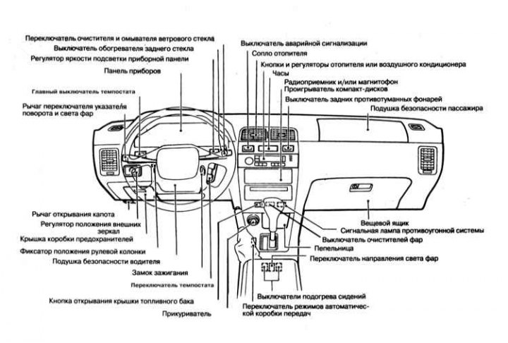
Controls located on the steering column, on the control panel, center and overhead consoles
The layout of some of the controls is shown in the illustration.
Left combined steering column switch for controlling the operation of external lighting / signaling devices
Switching on navigation lights and low / high beam headlights
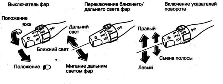
1. The main lighting control switch is made in the form of a lever mounted on the left side of the steering column directly below the steering wheel. 2. To turn on the outdoor lights, turn the end handle of the main switch lever to the first fixed position
3. Short-term switching of the headlights from low beam to high beam and back is done by pulling the switch lever towards you. To permanently turn on the high beam, move the lever away from you until it clicks, then release it.
Note. The high beam is switched on for a short time regardless of the position of the rotary end handle of the main switch. 4. Some of the models of cars considered in this Guide are equipped with a system for automatically switching on running lights during daylight hours (DRL). The daytime running lights turn on and off automatically when the ignition key is turned to the "ON", turning it off can be done by turning the end handle of the central light switch to the first or second fixed position.
Turning on the direction indicators
1. Turning on the indicators is done using the lever of the main lighting switch. The lever is moved up or down, depending on the selected direction of change of course. When moving the lever to the extreme upper/lower position (click) the corresponding direction indicators will continue to function until the steering wheel is returned to the straight-ahead position.
2. Short-term inclusion of indicators, for example, when intending to change lanes of movement, is done by slightly pulling the lever up or down, respectively.
Switching on the fog light
Note. Fog lights should only be used in conditions of poor visibility!
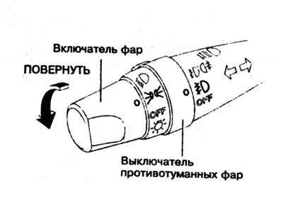
1. The fog lights are turned on/off by turning the ring switch on the lever handle of the left combination switch assembly to the appropriate position
 .
.
Note. Running lights must be on.
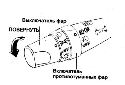
2. Turning on the rear fog lights is also done using the ring switch. Running lights must also be on.
Right combination stalk
Windshield wiper operation control switch
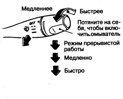
The windshield wipers/washers can only be switched on when the ignition is on (ON and ACC positions). The choice of operating modes of the wipers is made by moving the switch lever up / down. Parameters of the intermittent wiper operation (in the range 2-20) can be selected using the end handle at the end of the lever.
Attention! Washers should not be turned on for more than 30 seconds. Do not attempt to turn on the washer when the system tank is empty. In frosty weather, wipers should only be turned on after the windshield has warmed up.
Steering column switch for controlling the operation of the tempostat
Main switch of the speed control system
Speed control system (tempostat) included as standard on some models, optional on others. The system allows you to automatically maintain the selected cruising speed of the car without affecting the gas pedal. Cruise speed must not exceed 40 km/h. The use of the tempostat becomes especially convenient when driving for a long time on lightly loaded direct suburban highways. For safety reasons, it is not recommended to turn on the cruise control when driving in the city, on winding roads full of turns, on slippery road surfaces, in heavy rain or under other adverse weather conditions. In the cases listed above, the driver must be able to fully control the mode of movement of the car.
Attention! Incorrect use of the tempostat can cause an accident. Activate the cruise control system only when driving on open highways and in favorable weather conditions. During the operation of the system, automatic movement of the gas pedal may occur, which should not be held by the foot in order to avoid damage to the support and axle mechanisms.
The lever switch for controlling the functioning of the tempostat is located on the right above the steering column, below the assembly of the right combined steering column switch. The system is switched on/off by means of the button switch lever handle mounted in the end of the button and is accompanied by the operation of the corresponding control lamp on the vehicle instrument panel.
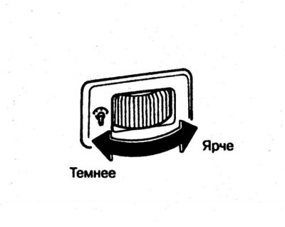
Dashboard illumination dimmer
The backlight brightness control is built into the dashboard of the car to the right of the steering column. The required panel backlight intensity is set by turning the potentiometer.
Note. The regulator starts to function only when the navigation lights are on (see above).
Regulator for adjusting the direction of the optical axes of the headlights
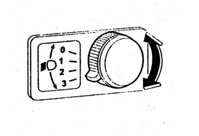
The regulator is located on the central console of the car between the keys of the seat heating switches and provides the ability to adjust the direction of the optical axes of the radiation of the headlights in the dipped beam mode and achieve the best conditions for lighting the road with different vehicle loads. Adjustment is made depending on the number of passengers, the presence and weight of cargo in the luggage compartment. The regulator should be moved to the position corresponding to the actual vehicle load or as close as possible to it:
- a) Position "0" - one driver or driver and passenger in the front seat;
- b) Position "1" - driver and four passengers in the front and rear seats;
- c) Position "2" - driver, four passengers in the front and rear seats, plus a load of about 185 kg in the luggage compartment (gross vehicle weight is within the allowable range);
- d) Position "3" - one driver and a load of about 380 kg in the luggage compartment (the loads on the front and rear axles of the car are within the permissible limits, the gross vehicle weight does not exceed the maximum permissible value). Also when towing a trailer.
Heated seats
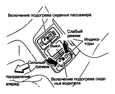
1. The front seats of the vehicle are equipped with built-in heaters. The seat heating control switches are located on the center console of the vehicle. 2. Start the engine, - turning on the heated seats with the engine turned off leads to a rapid discharge of the battery.
3. Use the selector button to select the required heating intensity mode (LO - low intensity or HI - maximum intensity). The corresponding indicator should light up on the button. The operation of the heater is controlled automatically by a thermostat. Remember to turn off the heating before leaving the vehicle.
4. Do not cover the seats with insulating materials such as blankets, ottomans, or hard covers. Do not place hard or sharp objects on the seats, take care not to damage the upholstery or the heating element underneath. Wipe up any liquid spilled on the seat with a dry cloth immediately. Do not use any solvents to clean the seat upholstery - use mild detergents. If the heater fails to function, contact a car service center for help.
Hazard light switch
1. The alarm is turned on by depressing the push-button switch mounted in the central part of the car's instrument panel (under the deflectors of the central air ducts for ventilation / heating of the passenger compartment) and usually equipped with a control lamp with a pictogram depicting two triangles inscribed one in the other. 2. Turning on the alarm leads to the simultaneous operation of all four direction indicators (and their control lamp on the dashboard of the car) The alarm system is designed to warn other road users about the forced stop of the car and is also used in other dangerous situations provided for by traffic rules.
Warning! When the alarm is on, the direction indicators will not function!
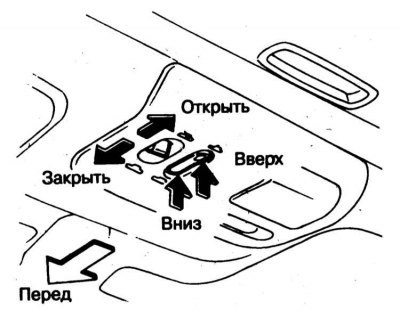
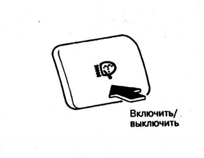
Top hatch drive operation control
1. The power sunroof operates only when the ignition is on.

2. The control panel for the functioning of the electric drive of the sunroof is located on the overhead console of the car. 3. To move the sunroof cover, press and hold the panel switch button marked with the
4. To tilt the sunroof cover, first fully close it, then press and hold the switch button marked with the
5. Additionally, the top hatch is equipped with a sunblind. When sliding the sunroof cover, the blind retracts automatically.
6. Make sure that passengers do not protrude into the sunroof while the car is moving. Before opening the sunroof, clean the cover of moisture, snow, dust and other foreign deposits. Do not place any heavy objects on the sunroof or roof surface near the sunroof.
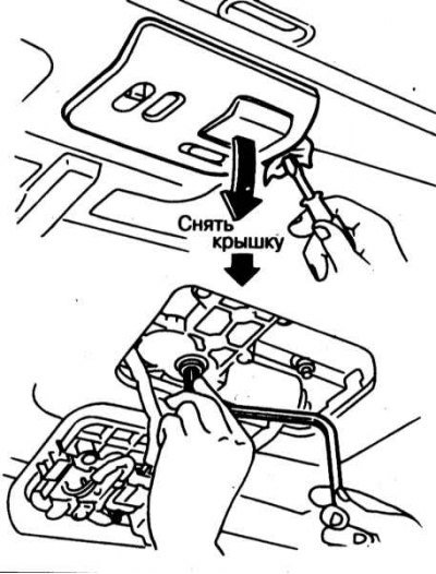
7. If the electric drive fails, the hatch cover can be moved to the closed position manually. Remove the lining of the control panel of the electric drive - access to the end of the drive motor shaft should open. Using a suitable size bar wrench, turn the shaft clockwise until the manhole cover is fully closed. To lower the lid from a tilted position, turn the shaft counterclockwise. To eliminate the causes of failure of the electric drive, contact a service station.
Electrically adjustable exterior mirrors

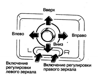
1. The assembly for controlling the functioning of the electric drive of the external rear-view mirrors is mounted in the instrument panel of the car, to the left of the steering column. The mirrors are adjusted using the slide and key switches of the panel as follows:
- a) Turn on the ignition (ON and ACC positions of the key);
- b) By moving the slide switch lever to the left (L) or right (R) select the mirror to be adjusted;
- c) By pressing the upper, lower, left or right sectors of the key switch, adjust the position of the selected mirror;
- d) After completing the adjustment of both mirrors, move the slide switch lever to the middle position, in which the adjustment button does not work. This is necessary so that if you accidentally press the button, the adjustment of the exterior mirrors will not be disturbed.

2. It is also possible to fold the mirrors into the parking position. To do this, push the mirror in the direction "back".
Heated rear window/outside mirror switch
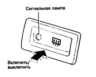
1. Turning on the electric heating allows you to remove condensation, frost, and even thin ice from the surfaces of the rear window / door mirrors. When the electric heater is turned on, the light indicator built into the switch button lights up. The heating is turned off by pressing the button again.
2. The filiform mesh of the heating element of the heater is glued to the inner surface of the rear window and requires care in handling - try not to damage the mesh when wiping the glass. Wiping should be done only along the heater threads.
3. The operation of the heater is associated with an increased level of energy consumption, therefore, in order to avoid the recharging of the battery, a timer is included in the control circuit of the device, which automatically turns off the system after 15 minutes of its continuous operation.
4. Do not forget to check the quality of the view through the rear window of the car before driving.
Electric drive of external rear-view mirrors
The assembly for controlling the functioning of the electric drive of the exterior rear-view mirrors is mounted in the instrument panel of the car, to the left of the steering column. The mirrors are adjusted using the slide and joystick switches of the panel as follows:
- a) Turn on the ignition (ON and ACC positions of the key);
- b) By moving the slide switch lever to the left (L) or right (R) select the mirror to be adjusted;
- c) Use the joystick switch to correct the position of the selected mirror;
- d) After completing the adjustment of both mirrors, move the slide switch lever to the middle position, in which the adjustment button does not work. This is necessary so that if the button is accidentally pressed, the adjustment will not be disturbed.
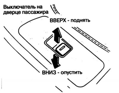
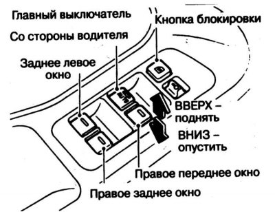
Power windows
The power windows operate only when the ignition is on. To lower/raise the glass, use the corresponding individual switch. It is possible to control the windows of all doors from the driver's seat. A button is also provided to allow the driver to override all passenger door controls. To disable the lock, press the lock button again. To lower/raise the window, press and hold the relevant switch key.
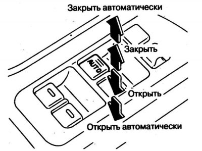
It is possible to automatically transfer the glass of the driver's door to one of the extreme positions (fully open or fully closed), briefly press the AUTO button on the driver's door control panel. To pause the process of opening/closing the glass, press the button again.
Headlight lens cleaner/washer switch

The push button switch is mounted in the center trim section of the vehicle's instrument panel between the tempostat switch and the anti-theft warning lamp. The system is activated only when the ignition is on. Fluid is supplied to the headlight lenses from the same reservoir as the windshield - periodically check its level.
Attention! Turning on the washers when the tank is empty is fraught with failure as a result of overheating of the electric motor of the submersible pump!
Tempostat operation control
Attention! Do not use the cruise control when driving on busy roads, on serpentines, in hilly and mountainous areas, with slippery road surfaces and strong winds.
1. Speed control system (tempostat) provides the ability to automatically maintain the speed of the car in the range from 48 to 160 km / h without using the gas pedal.
2. To turn on the tempostat, move the main switch located on the dashboard of the car to the left of the steering column to the ON position.
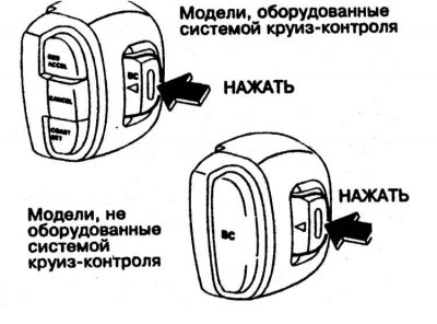
3. Accelerate the car to the required speed and press the SET / COAST button on the control panel for the operation of the tempostat, - the word CRUISE should light up on the on-board processor display.
4. Take your foot off the accelerator pedal. The system will automatically maintain the selected cruising speed of the vehicle.
5. To overtake, depress the gas pedal. After the pedal is released, the vehicle will return to the previously selected cruising speed.
6. When driving downhill or uphill, the tempostat does not maintain the cruising speed of the vehicle and must be turned off.
7. Cancellation of the selected cruising speed can be done in three different ways:
- a) Press the CANCEL button (Cancel), - the inscription CRUISE should go out;
- b) Slightly depress the foot brake pedal, - the inscription CRUISE
- c) Use the main switch of the tempostat - the inscription CRUISE and the control lamp mounted in the switch key should go out.
8. If the foot brake pedal was depressed while pressing the ACCEL key of the control panel, turn off the tempostat with the main switch and activate it again after reaching the required speed.
9. The thermostat switches off automatically when the vehicle speed drops to 13 km/h
10. Switching off the speed control system can also be done by depressing the clutch pedal (models with manual transmission) or moving the selector lever to position "N" (models with AT).
11. Increasing the cruising speed of the car can be done in three ways:
- a) Depress the accelerator pedal, when the vehicle accelerates to the desired speed, press and release the SET/COAST button on the control panel;
- b) Press and hold down the ACCEL button on the tempostat operation control panel. Release the button when the vehicle has reached the desired speed;
- c) By briefly pressing the ACCEL button, you can accelerate the car in increments of 1.6 km/h.
12. To reduce cruising speed:
- a) Lightly depress the foot brake pedal. When the vehicle speed drops to the required value, press the SET/COAST button;
- b) Press and hold the SET/COAST button until the vehicle has braked to the desired speed;
- c) By briefly pressing the SET/COAST button, the vehicle's cruising speed can be reduced in steps of 1.6 km/h.
13. To return to the previously selected cruising speed, briefly press the RESET button. As soon as the car accelerates over 48 km / h, the tempostat will automatically bring it to the previously selected cruising speed, which it will continue to maintain.
Adjustable steering column release lever
Note. See information regarding the correct and safe position of the steering column. 1. The position of the steering column on cars of the corresponding configuration can be adjusted at the discretion of the driver. Adjustment is carried out before the start of the movement.
Attention! Performing a steering column adjustment while driving may result in loss of control of the vehicle and may result in serious accidents!
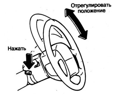
2. In order to adjust the position of the steering column in height, you must:
- a) Lower the steering column lock lever located on the left under the steering wheel to the stop;
- b) Adjustment of the position of the steering wheel in height is carried out by moving it to the desired position in the vertical plane. A properly adjusted steering wheel should not block the view of the instrument panel;
- c) Upon completion of the adjustment, fix the steering column by fully returning the lock lever to its original position;
- d) Check that the column is secure by trying to move it up and down.
Parking brake lever
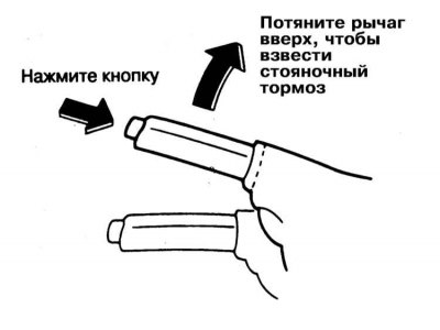
To apply the parking brake, fully lift up the lever located between the front seats. The parking brake is released as follows: slightly pull the lever up, press the release button located on the end of the handle, then lower the lever down. When the parking brake is released, the corresponding control lamp mounted in the vehicle's instrument panel should go out (see above in this Section).
Attention! Driving with the parking brake applied can lead to failure of the brakes and rear wheel bearings!
Shift lever/gear selector
Models with manual transmission
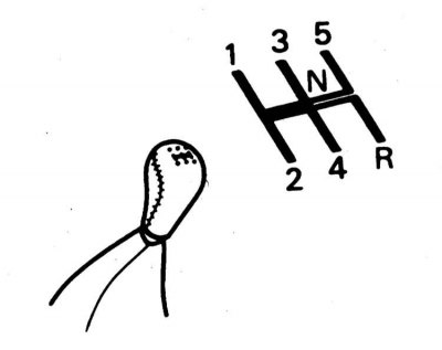
The manual transmission shift lever is located on the center console of the car. On top of its handle is a gear shift pattern.
Models with AT
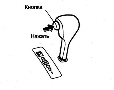
The AT gear selector lever is also located on the center console of the vehicle. On the side of the lever handle there is a button to release the lock, which should be squeezed out when switching the transmission to the positions "R", "R", "2" And "1".
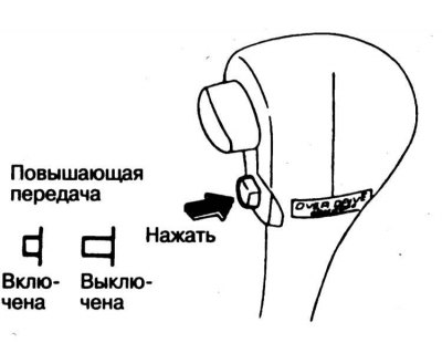
Below the override switch is the overdrive switch (O/D). When pressing the button "O/D" overdrive is disengaged (control lamp lights up at the same time "O/D OFF"). To turn O/D on, press the button again.
Note. The overdrive only functions when the engine is warmed up to normal operating temperature. When the tempostat is on, the overdrive disable button is no longer valid.
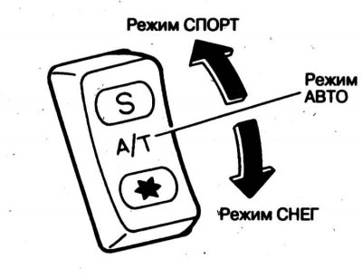
On models with AT, it is possible to select the modes of operation of the transmission. The mode switch button is located on the center console of the car, to the left of the AT selector lever and allows you to select one of the following three modes: AUTO, SNOW and SPORT (see Section Operating techniques).
Seat adjustment
Front seats
Manual seats
1. Section Elements of car security systems provides important information on safety and correct adjustment of seats, seat backs and head restraints.
2. Before driving, adjust the seat.
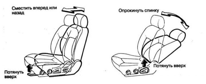
3. To adjust the seat longitudinally, pull up on the brace located at the front under the seat cushion and, while holding it up, slide the seat assembly forward or backward to a position that is comfortable for you. Release the bracket, to check the reliability of the fixation of the seat, try to move it back and forth.
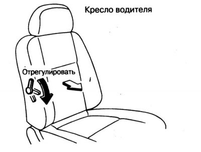
4. To change the angle of the seatback, pull it forward, lift the lever located on the side of the seat cushion base on the door side, then, while holding the lever up, adjust the backrest. The backrest locks into the new position automatically when the lever is released.
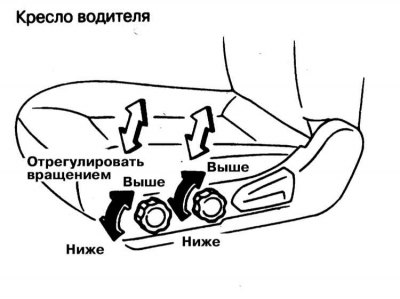
5. Some vehicle versions provide the ability to adjust the height of the seat cushion. Adjustment is made using two handles located on the outside of the pillow.
Models with power driver's seat adjustment
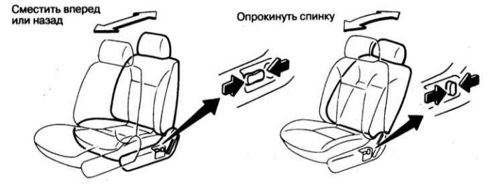
1. Some models are equipped with an electric driver's seat adjustment. The control panel for the functioning of the electric drive with two switches is located on the left side surface of the seat cushion. The combined extended slide switch serves to adjust the position of the seat in the longitudinal and vertical directions. The smaller switch adjusts the backrest angle.
2. Seat adjustment can be carried out at any position of the key in the ignition lock and must be performed before driving.
3. To adjust the position of the seat in the longitudinal direction, move the extended slide switch on the control panel for the operation of the electric drive in the appropriate direction.
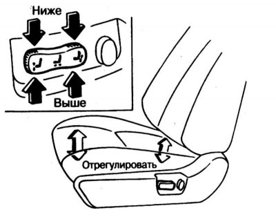
4. Adjusting the height of the position of the front and rear edges of the seat cushion is carried out by pressing the front or rear ends of the slide switch in the appropriate direction (1). Adjusting the height of the cushion assembly is done by moving the entire switch up or down.
5. Backrest adjustment is done with a smaller switch (2), located behind the first elongated switch.
6. Adjustment of the amount of curvature of the lumbar back (with appropriate equipment) It is made by means of the lever located assembly on a back of a seat.
Seat heating
Some models have heated front seats (see above).
Note. Do not turn on the heated seats when the engine is not running and try not to use it for a long time when the engine is idling to avoid discharging the battery.
Backseat
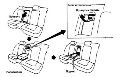
On some models, the rear seat is equipped with a center armrest. The armrest is located in the central part of the seat and unfolds by removing it from a niche in the backrest and lowering it to a horizontal position. After lowering the armrest, access to the luggage compartment of the car opens.
Headrests
Head restraints help prevent neck and head injuries in a rear-end collision. In order for head restraints to perform their protective functions effectively, they must be properly adjusted. Adjust the height of the head restraints so that the top of the head restraint cushion is flush with the top edge of the ear. If this condition cannot be met by tall passengers, the head restraint should be set to the highest possible position.
On some modifications of the car, it is possible to adjust the headrests in height and angle of inclination. The head restraint is adjusted with both hands at the same time, so do not attempt to adjust the head restraint while the vehicle is moving. To raise the head restraint, simply pull it up; to lower it, push it down; changing the angle of the headrest is done by bending it to the appropriate position.
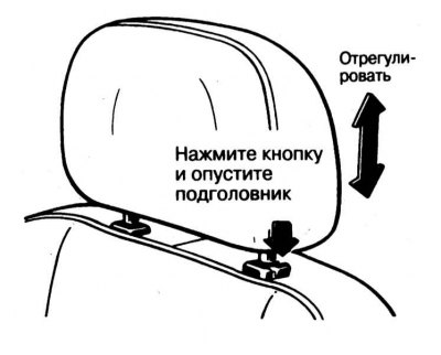
Some versions of the car provide for the presence of a push-button head restraint. With this design, in order to raise the head restraint, it is enough just to pull it up, while lowering can only be done after depressing the lock button.
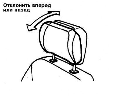
The headrest angle is adjusted manually.
Rear view mirrors
To ensure an adequate view of the area behind the vehicle, keep it clean and check that the interior and exterior rear-view mirrors are correctly adjusted. Before driving, make sure that the rear-view mirrors are properly adjusted.
Interior rear view mirror
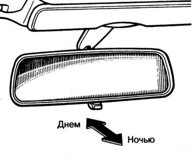
There are two regular positions of the internal rear-view mirror: one is intended for movement in the daytime, the other - in the dark. In the second position, the reflectivity of the mirror is reduced, which helps to reduce the blinding effect of the headlights of vehicles moving behind. The transfer of the mirror of the day position to the night position and vice versa is carried out using a special lever built into the assembly from below. Press the lever forward or backward to select the desired mirror position.
Exterior mirrors
The principle of operation of the electric drive of external rear-view mirrors is set out in the second subsection of this Section (see above).
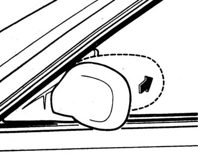
It is also possible to fold the mirrors into the parking position. To stow the rear view mirror into the parking position, simply press it against the glass of the car door.
Clock/thermometer
The clock is mounted in the upper part of the central section of the instrument panel and functions only when the ignition is on, or in the ACC key position.
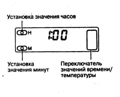
Setting the hourly readings is done using the button "H", minute - using the button "M".
After disconnecting the battery, the clock is automatically reset to zero and must be adjusted.
Note. When the instrument panel lighting is turned off, the clock indicator will dim.
The clock display is also used to display the readings of the outdoor temperature meter. The display operation mode switch is located on the left side of the clock assembly.
Onboard processor display

With the appropriate vehicle configuration, the on-board processor display is mounted in the tachometer dial. With the ignition on, you can select one of the possible display modes. The selected mode is indicated by a special cursor in the form of a triangle. The display can be used to show time, outside temperature, distance that can be driven without refueling, trip distance, travel time, average speed and average fuel consumption.
Switching display modes is carried out by a special button.
Air temperature is measured in degrees Celsius. When the temperature drops below 3°C, the display automatically switches to thermometer mode, while its readings begin to flash, attracting the driver's attention. Pressing the mode switch returns the display to its original mode. At temperatures below 4°C, the thermometer cursor continues to flash continuously.
When you turn on the display mode for the distance that can be traveled without refueling, the display changes every 30 seconds. There is a function to automatically switch the display when a critical minimum fuel supply is reached. The display also flashes to attract the driver's attention. The cursor will continue to flash until the vehicle has been filled up. With a further decrease in the fuel level, the display readings are reset to zero and the display shows the value "----".
When the trip display mode is enabled, the display can be reset by holding the switch pressed for 1 second. At the same time, the travel time will be reset (see below).
To reset the drive time, hold the switch button pressed for at least 1 second. At the same time, the distance traveled is reset.
In the average fuel consumption mode, the display changes every 30 seconds. To reset the readings, keep the switch button pressed for 3 seconds. During the first 500 meters of movement after the reset, the display will show the value "----".
In medium speed mode, the display will also change every 30 seconds. The readings are reset by holding the switch button pressed for a second. During the first 30 seconds after the reset, the display will show the value "----". Resetting the average speed also resets the average fuel consumption reading.
Business card holder and cup holder
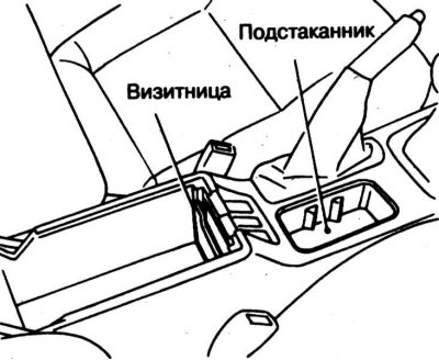
The business card holder and cup holder are built into the center console assembly behind the parking brake control lever.
When using the holder, be careful not to burn yourself or burn other passengers with hot drinks. Be aware that many drinks can ruin the look of floor mats, seat upholstery, and door interior panels. Liquid splashes on electrical contacts can cause damage to the passenger compartment electrical equipment.
Center console storage box
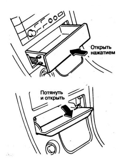
In front of the center console, under the audio system assembly, a small storage box is mounted for storing small items. There are two designs of a small glove box - retractable and reclining.
Cigarette lighter and ashtrays
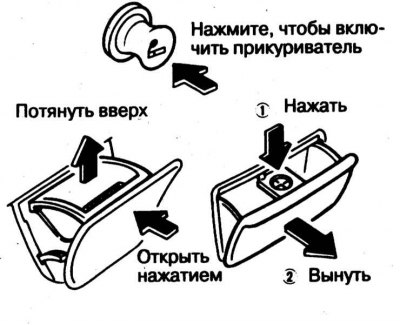
The cigarette lighter functions only with two key positions in the ignition lock: "ACC" or "ON", when the ignition or auxiliary power consumers are on. To turn on the cigarette lighter, press the button until it clicks. After heating the spiral, the button will automatically return to its original position with a click.
Attention! To avoid the cigarette lighter failure, do not hold its button while heating the coil!
The front ashtray is combined with a single assembly with a cigarette lighter, the rear one is located under the center armrest assembly.
Sun visors
Two fold-down sun visors are located above the top edge of the vehicle's windshield to protect the eyes of the driver and front passenger from direct sunlight. If the rays fall from the front, the visor should simply be lowered by turning it down on the axial hinges. To protect against light falling from the side, the visor should be released from the inner loop and turned towards the door. If necessary, the visor can be extended by pulling out an additional shield.
Attention! Pulling out the additional shield in the first position of the sun visor can cause the rear-view mirror to close!
Vanity mirror
The vanity mirror is installed in the sun visor and is protected by a cover.
Interior lighting devices
Main saloon lamp
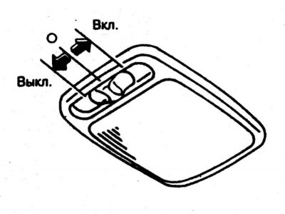
1. Front switch (chief) The interior lamp has three fixed positions. Pregnant "0" interior lighting is switched on when any of the interior doors are opened.
2. The built-in timer automatically turns on the lighting for 30 seconds in the following cases:
- a) When the driver's door is not locked with the ignition key removed;
- b) When the key is removed from the ignition with the driver's door closed;
- c) When the driver's door opens and then closes again with the key removed.
3. The lighting is automatically turned off by a timer when the driver's door is locked and the ignition key is turned to the ON position.
Local lighting fixtures
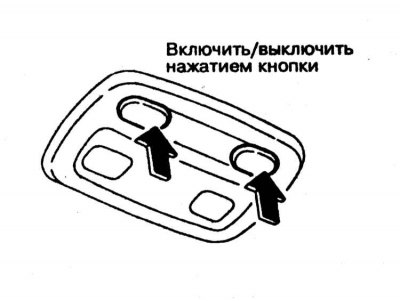 | 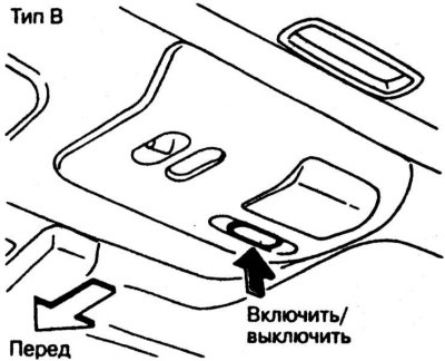 |
Two directional individual lamps are also mounted in the ceiling console of the car. Switches for individual lamps are located next to the ceiling lamps of the corresponding lamps (left and right). To turn on the lamp, press the button of the corresponding switch. To turn off the lighting, press the same button again. Individual lamps function in any position of the key in the ignition lock.
Ignition light
On some models, the ignition switch is illuminated. The backlight turns on when the driver's door is opened and stays on for a few seconds after it is closed.
Power take-off socket
The power take-off socket is designed to supply power to auxiliary electrical appliances. The key must be turned to the ON or ACC position.
Attention! The voltage of the onboard power supply is 12 volts, do not connect consumers with parameters higher than 12 V / 120 W to the power take-off socket. An unused socket should be covered with a special cover.