


Warning! The vehicles covered in this Manual are equipped with an additional SRS safety system, better known as an airbag. Before performing any work in the vicinity of the airbag or steering column assembly, be sure to disconnect the system to avoid injury if it is accidentally triggered. Disconnect the negative and then positive wires from the battery and wait at least two minutes before servicing components located near the directional overload sensors (see A chapter On-board electrical equipment). The insulation and connectors of the SRS circuit wiring are painted bright yellow. Do not connect any diagnostic equipment to this circuit!
The materials in this Section apply only to models with manual control of the heater and air conditioner. In the event of a fan failure on models equipped with a climate control system, the car should be taken to a service station for diagnostics and repair of the relevant components.
1. If the heater fan fails or malfunctions, first check the condition and reliability of all terminal connections of the corresponding electrical circuit. Make sure the battery is fully charged. Assess the condition of the corresponding fuse, relay, switch. The possibility of failure of the drive electric motor cannot be ruled out.
2. Before you start checking the electric motor itself, be sure to evaluate the condition of the fuse and relay (if such is provided) (See Chapter On-board electrical equipment).
3. To gain access to the heater housing and fan assembly, remove the glove box and lower instrument panel trim section (see Chapter Body).
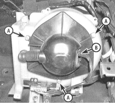
4. Turn the ignition key to the ON position and move the heater fan control switch to the failure position(s). To check the correctness of the power supply to the electric motor, you will need a test lamp or voltmeter. If the voltage is supplied correctly, you should check the condition of the motor ground circuit (in the models under consideration, the control switch and resistor assembly are part of the grounding circuit). The possibility of the impeller jamming cannot be ruled out either.
5. To check the quality of grounding, disconnect the wiring from the electric motor and connect a jumper wire between the motor ground terminal and a reliable ground. Use a second jumper wire to connect the positive terminals of the motor and battery. If the fan starts to rotate properly, there is a problem with the grounding quality, or the resistor assembly has failed. Otherwise, replace the motor or eliminate the cause of the impeller jamming.
6. To identify the reasons for the impeller jamming, remove the electric motor assembly (see section Removal and installation the electric motor of the heater fan drive).
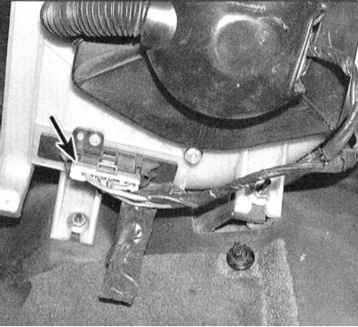
7. If the grounding quality is poor, check the condition of the resistor assembly located in the casing next to the electric motor.
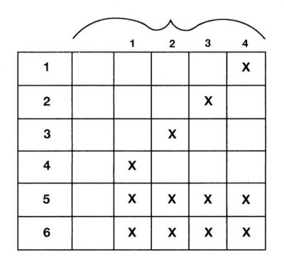
8. Using an ohmmeter, check the quality of the grounding of the resistor assembly in various positions of the control switch - in each position (except OFF) conductivity should exist between three of the six terminals.
9. If any faults are detected, appropriate repairs should be made to the switch or the wiring leading to it.
10. If the grounding is good, check the resistor assembly for conductivity between the terminals. If a break is detected, replace the resistor.
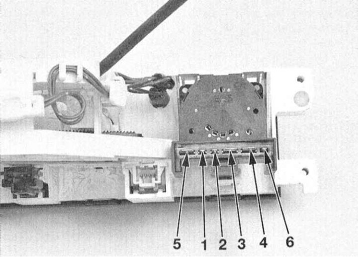
11. For a description of the procedures for checking the operation of the fan speed selector switch, see Section Removal and installation the heater and air conditioner control panel assembly, adjusting the drive cable. To gain access, remove the heater/air conditioner control panel from the dashboard.
12. Disconnect the wiring and use an ohmmeter to check the correct distribution of conductivity between the terminals of the switch connector.
13. If any faults are found, replace the switch.