Attention! The air conditioning system is constantly under high pressure. Never disconnect refrigeration lines or remove any system components without first discharging the system. The discharge of the air conditioning system must be carried out by an experienced specialist in a car service workshop. Always wear safety goggles when disconnecting refrigerant lines!
When replacing air conditioning system components, a certain amount of replacement refrigerant oil will be required to fill the volume of the new assembly. Use only oil suitable for use in R-134a systems (read the label on the container carefully). Remember that seals designed for use in systems filled with R-12 oil are not suitable in this case.
Service
1. The following checks should be carried out on a regular basis to keep the air conditioning system in good condition:
- a) Check the condition of the compressor drive belt. If defects or signs of wear are found, replace (see chapter Settings and ongoing maintenance);
- b) Check drive belt tension, adjust if necessary (see chapter Settings and ongoing maintenance);
- c) Check the hoses of the refrigeration path for cracks, swelling, signs of hardening and aging of the rubber, evaluate the condition of the fittings. Replace defective components;
- d) Check the condenser coil plates for insect debris, old leaves, and other debris stuck between them. If necessary, clean the gaps with a thin brush, or blow them with compressed air;
- e) Check system charge level;
- f) If there are leaks of liquid in the area of the instrument panel, or on the rugs, check the patency of the evaporator drain tube.
2. The air conditioning system must be turned on for at least 10 minutes at least once a month (even in the winter season). Prolonged inactivity of the A / C leads to hardening and failure of the sealing rings and cuffs of the connecting path.
3. Due to the complexity of the system design and the need to use special equipment, its maintenance, in-depth diagnostics and refurbishment are beyond the qualifications of an average amateur mechanic and must be carried out in a car service workshop. Only the simplest checks and replacements listed below in this Section fall within the competence of the owner of the car.
4. The most typical reason for a malfunction of the A/C operation is a decrease in the charge level of the refrigerant oil.
5. The following simple checks will quickly identify signs of a low refrigerant level.
Examination
1. Warm up the engine to normal operating temperature.
2. Turn on the A/C for maximum cooling capacity. Select the maximum fan speed. Open the doors to avoid cycling the system when the enclosed air volume in the cabin cools.
3. After the temperature of the system reaches the operating temperature, feel the two tubes connected to the evaporator on the bulkhead of the engine compartment.
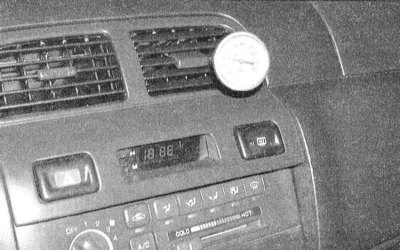
4. The thinner tube leading to the evaporator from the condenser outlet should feel cold enough to the touch. The thicker tube from the evaporator outlet back to the compressor should be a little more (2 - 6 degrees) colder. If the exhaust pipe is noticeably warmer to the touch than the inlet, then the system needs to be recharged. Insert the thermometer into the air outlet duct through the central vent on the instrument panel. When the A/C is on, the temperature of the air leaving the deflector should be 19 - 22 degrees below the ambient temperature (up to 4.5°C). In very hot weather (40°C), it is permissible to increase the output temperature to a level of 15.7°C, but no more. If the air conditioner does not provide the required intensity of air cooling, the system should be recharged. For a more detailed diagnosis of the state of the system, the car should be driven to a specialized workshop.
5. If the intensity of cooling of the air supplied to the passenger compartment is insufficient, the system probably needs to be recharged.
6. If there are signs of complete system failure, check the compressor clutch for proper operation.
7. Watching the front of the compressor, have an assistant turn on the A/C. the clutch should make a distinct click, and its central part should begin to rotate, otherwise stop the engine and disconnect the system pressure switch. Connect the connector terminals with a jumper wire and turn on the air conditioner again. If now the system begins to function properly, therefore the pressure in it is excessively high or low, drive the car to a service station.
8. If the clutch still does not work, check the condition of the appropriate fuses in the mounting block located in the passenger compartment.
9. Remove the compressor clutch relay from the mounting block located in the engine compartment and check its operation (see chapter Onboard electrical equipment). With the relay removed and the ignition on, check the power supply to the two relay terminals in the mounting block (see wiring diagrams at the end of the Chapter Onboard electrical equipment).
10. Using a jumper wire, connect the power terminal of the compressor clutch relay in the mounting block (see wiring diagrams) to the corresponding clutch terminal - the clutch should make a click. If there is no click, disconnect the electrical wiring from the clutch and check the power supply to its connector. Check the ground terminal on the black wire of the connector. If the wiring is OK, replace the compressor clutch assembly.
11. If all components and wiring are in order, and the system is charged to the required level, you should drive the car to a service station for diagnostics and repair of the PCM.
12. A more detailed diagnosis of the air conditioning system is beyond the skill of the average amateur mechanic and should be entrusted to car service specialists.
Adding refrigerant
Attention! To charge the air conditioning system of the vehicles covered in this manual, use only refrigerant oil R-134a.
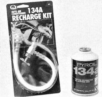
1. Prepare the standard charging kit R-134a (ask at car accessories stores). Kit includes 12 oz refrigerant oil can (ounce), a valve nozzle and a piece of hose connected between the valve and the fitting of the low-pressure part of the refrigeration path. Since one can of oil may not be enough to fully charge the system, it makes sense to buy a couple at once just in case. Make sure that at least one of the cans is tinted with red oil, which will allow you to quickly identify refrigerant leaks if they occur.
Attention! Never fill the system with more than two cans of refrigerant!
2. Connect the charging kit to the LOW PRESSURE section of the refrigeration circuit, following the manufacturers instructions.
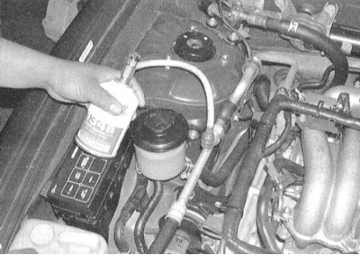
3. Close the valve on the adapter and screw the adapter onto the cartridge head, making sure that the o-ring/rubber gasket is present.
Attention! Be sure to wear safety goggles!
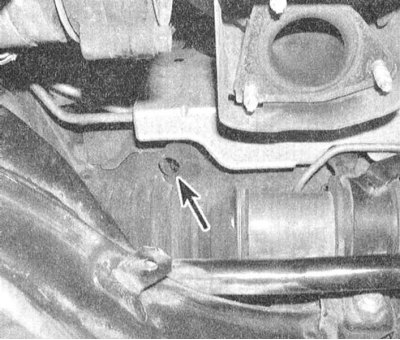
4. Remove the dust cap from the low-pressure refrigeration line connection and connect the charging set hose equipped with a quick connector to it.
Attention! The design of the choke units will not allow the connection of the set to the high-pressure part of the tract.
5. Warm up the engine to normal operating temperature and turn on the A/C. Make sure that the charge kit hose does not come into contact with the engine cooling/air conditioning fan blades and other moving components in the engine compartment.
Note. Charging the system must be done with the compressor running. If the compressor clutch disengages, the system should be switched to maximum cooling capacity and all passenger compartment doors should be opened.
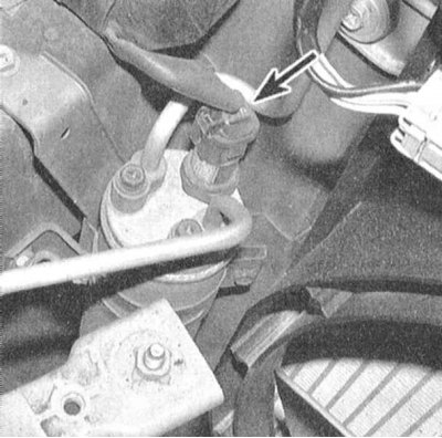
To prevent the compressor from turning off during charging, disconnect the connector from the low pressure switch (some models use a combined low/high pressure sensor/switch) and bridge it with a paper clip or a piece of stiff wire.
6. Rotate the valve nozzle to pierce the head of the cartridge, thereby opening the refrigerant supply (you should hear the characteristic sound of escaping gas). During the entire charge, hold the can strictly upright, shaking it from time to time. Between charging series, pause to allow the system to stabilize.
Note. Never add more than two bottles of refrigerant to the system! Wrap a towel soaked in warm water to prevent icing on the can during refilling.
7. If you have an accurate thermometer at hand, insert it through the deflector into the central air duct K / V and monitor the temperature of the air supplied to the passenger compartment.
8. When the cartridge is empty, close the valve and disconnect the hose from the system's low-pressure connection. Replace the dust cap immediately.
9. Disconnect the valve nozzle from the cartridge, if necessary, move it to the second cartridge and continue filling. Upon completion of the procedure, place the unfinished cartridge upright on the rack and use it as needed to recharge the system.
Heating system
1. Moistening of the carpet on the floor under the heater's heat exchanger, or steam escaping through the air duct deflectors indicate heat exchanger leaks. Remove heat exchanger (see Section Removal and installation of the heater heat exchanger) and replace it with a new one (the heater heat exchanger cannot be repaired).
2. If the heater does not provide proper heating of the air supplied to the cabin, the reason for such a failure may be one of the following:
- a) The thermostat is stuck open, preventing the engine coolant supply to the heater heat exchanger from reaching normal temperature. Replace thermostat (see Section Check of serviceability of functioning and replacement of the thermostat);
- b) There is a violation of the patency of the cooling tract, which blocks the supply of coolant to the heater heat exchanger. Feel the hoses connected to the nozzles on the rear bulkhead of the engine compartment - both of them must be hot, otherwise the patency of the tract is broken (blocked hoses, heat exchanger, or heater control damper). Disconnect the hoses and back-flush the heat exchanger. Having previously disconnected, also flush both hoses;
- c) If it is not possible to restore the patency of the heat exchanger by flushing, it should be replaced (see Section Removal and installation of the heater heat exchanger).
Eliminate air conditioning odors
1. Unpleasant odors that often occur when A/C is turned on are caused by the formation of mold colonies on the evaporator heat exchanger plates. A warm, humid environment creates favorable conditions for the emergence and development of fungal microorganisms.
2. Access to the evaporator coil is extremely limited on most models. The procedure for guaranteed complete removal of mold, performed in a car service workshop, is quite laborious, time-consuming and requires the use of strong disinfectants. In principle, sufficiently effective processing can be performed at home by the owner of the car on his own.
3. Specialty aerosol disinfectants designed for servicing air conditioning systems are available from almost any automotive accessory store. It should be remembered that the price of a tool is usually directly proportional to its effectiveness. Switch the system to closed air circulation mode and turn on the heater fan at maximum speed for ten minutes. In order to dry the system, turn on the heating to maximum intensity. Disconnect the electrical wiring from the compressor to prevent it from tripping.
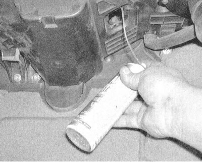
4. The supply of the agent is usually carried out through a long hose. Remove the heater fan motor resistor assembly (see Section Removal and installation of the electric motor of the heater fan drive), insert the nozzle of the supply nozzle into the resulting hole and move it to the left, pointing at the evaporator heat exchanger. The supply of the product is carried out in accordance with the instructions of its manufacturer. Try to treat the entire surface of the heat exchanger as completely as possible. The duration of each processing cycle and the intervals between series must be indicated on the container label.
5. The best preventive measure against mold colonization in the evaporator heat exchanger is to regularly check the patency of the drain pipe, and briefly turn on the condensate removal mode after each long trip with the air conditioner running to dry the evaporator.
Climate control system
The optional equipment of Nissan Maxima vehicles may include a climate control system. The functioning of the system is controlled by its own processor, which receives the necessary input data from various information sensors. Like the PCM, this processor includes a self-diagnostic unit for quick troubleshooting. The operator selects the required temperature regime and sets it using a special handle on the control panel. Then the system starts to automatically maintain the set air temperature in the passenger compartment, adjusting the supply of cold and/or warm air accordingly. The speed mode of the fan operation is also controlled by the microprocessor through a controller connected in series, which in this case replaces the resistor assembly. Complete failure diagnosis and repair of the climate control system is beyond the skill of the average amateur mechanic. However, the processor is equipped with an on-board self-diagnosis device with the ability to display fault codes.