Warning! Avoid touching the impeller blades with your hands, tools and clothing. To avoid personal injury or property damage, do not start the engine with a defective fan. Do not attempt to repair broken impeller blades - change it as an assembly!
Examination
1. All models are equipped with a two-speed cooling fan assembly housed in a plastic shroud mounted behind the heatsink.
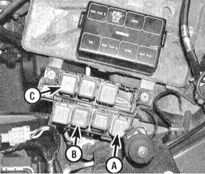
A - Low speed relay
B - High speed relay No. 1
C - High speed relay No. 2
2. Fan operation is controlled by PCM through a set of speed control relays. The ECT sensor informs the PCM about the current coolant temperature and the module, based on the analysis of the incoming data, switches on the appropriate fan speed. At idle, the low speed mode is activated. When the liquid temperature reaches 106°C, the PCM activates high-speed mode No. 1 or No. 2. The presence of the second high-speed mode ensures that the fans operate properly even if one of the relays fails. The relays continue to function properly even if the ECT sensor fails.
3. If the fan continues to run continuously, check the condition of the relay and coolant temperature sensor. A description of the sensor diagnostics procedure is given in Chapter 6. Relay diagnostics is described in Chapter Onboard electrical equipment.
4. Warm up the engine to normal operating temperature - the fans should turn on, otherwise check the condition of the appropriate fuses in the mounting block located in the engine compartment or in the car (see chapter Onboard electrical equipment).
5. If the fuses are OK, disconnect the electrical wiring from the fan drive motor. Using a fused jumper wire, connect either of the two motor power terminals to the battery. Ground the black wire terminal to ground. If the fan does not work, it should be replaced.
6. If the fan works properly when powered directly from the battery, connect a voltmeter to chassis ground and test both motor power terminals on the harness side. With the engine warmed up to normal operating temperature (according to the readings of the temperature meter in the instrument panel) one of the terminals should have battery voltage.
7. Using an ohmmeter, check the condition of the ground loop - there should be no more than 5 ohms between the black wire terminal and the chassis ground. At higher instrument readings, the cause of the violation should be determined and eliminated.
8. If during the test described in paragraph 6 there is no power at the connector terminals, check that power is being supplied to the low grade relay. On one of the receiving terminals of the relay socket, the battery voltage must be constant, on the other, only in the ON or START position of the ignition key.
9. If power is supplied to the socket properly, check the conductivity of the relay itself (see chapter Onboard electrical equipment).
Replacement
1. Disconnect the negative cable from the battery.
Attention! If the stereo system installed in the car is equipped with a security code, before disconnecting the battery, make sure that you have the correct combination to activate the audio system!
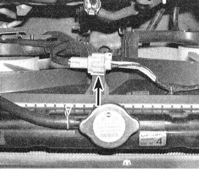
2. Disconnect the top and overflow hoses from the radiator.
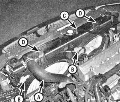
3. Turn out two bolts of fastening of a casing and remove fan assembly from the car.
Note. The lower part of the casing is attached to the radiator by means of clamps.
4. Loosen the nut securing the impeller to the motor shaft.
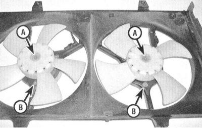
5. Turn out screws of fastening of the motor to a casing.
6. Using an assistant, tap the motor shaft out of the housing assembly with a hammer.
7. Installation is carried out in the reverse order.