The location of the components of the cooling, heating and air conditioning systems in the engine compartment of the car
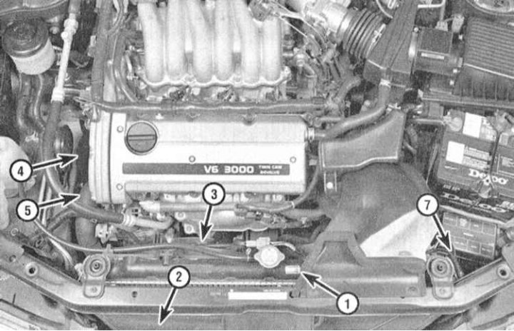
1 - Radiator; 2 - Capacitor; 3 - Fan of the cooling system; 4 - Water pump; 5 - Thermostat; 6 - Expansion tank; 7 - Accumulator/dryer
Thermostat components
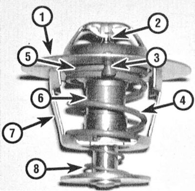
1 - Flange; 2 - Piston; 3 - bleed valve; 4 - Main helical spring; 5 - valve seat; 6 - Main valve; 7 - Frame; 8 - Secondary helical spring
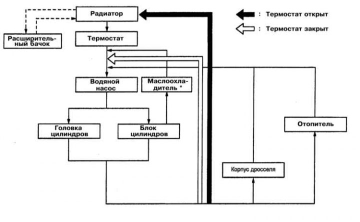
Coolant circuit diagram with DOHC engines
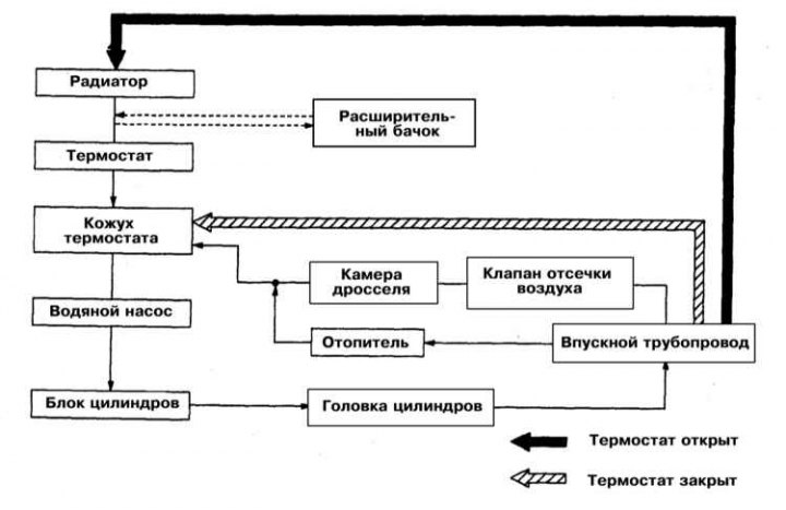
Scheme of coolant circulation with SOHC engines
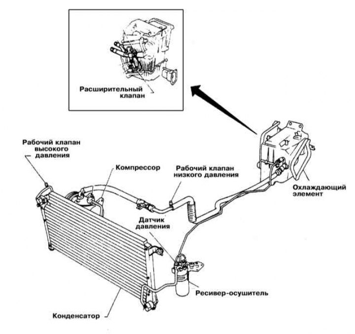
Schematic diagram of an air conditioning system
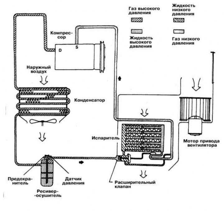
Functional diagram of the air conditioning system
Engine cooling system
All models of vehicles discussed in this manual are equipped with a positive pressure engine cooling system with thermostatically controlled circulation of the working fluid. The water pump of the rotary type is fixed on the engine block and provides pumping of the coolant through the cooling path of the latter. The flow of fluid washes the areas where each of the cylinders in the block is located and is directed to the rear of the engine. Cast-in-the-block and cylinder-head cooling ducts provide intensive cooling for intake and exhaust ports, spark plug areas and exhaust valve guides.
The wax-filled thermostat controls the operating temperature of the engine during engine warm-up. In the first minutes after starting a cold engine, the thermostat remains closed, thereby preventing the circulation of coolant through the radiator. When the engine temperature reaches normal operating temperature, the thermostat valve opens, connecting a radiator to the cooling circuit, ensuring maximum heat removal from the working fluid (coolant).
The cooling system is hermetically sealed and tightly sealed with a radiator cap capable of withstanding a certain overpressure, which increases the boiling point of the coolant and, accordingly, the efficiency of heat removal through the radiator. When the internal pressure in the system exceeds a certain value, the spring-loaded plate of the safety valve mounted in the radiator cap rises above its seat, ensuring that excess coolant flows through the connecting (overflow) tube into the expansion tank. As the system cools down, the fluid automatically returns from the reservoir to the radiator.
Coolant is added to the system through the neck of the expansion tank, which at the same time also acts as a receiver that accumulates excess liquid displaced from the radiator.
In view of the above design features, such a cooling system is called closed, since it excludes any functional loss of coolant.
Heating system
The main components of the interior heating system are an electric fan and a heat exchanger located in the box-shaped casing of the heater. The heat exchanger is connected to the engine cooling system via rubber hoses. The control unit for the functioning of the heater / air conditioner is mounted in the instrument panel of the car. The coolant heated in the engine circulates through the heater heat exchanger, giving off its heat to the air filling the casing. When the interior heating is turned on, the leaf damper opens, as a result of which the internal volume of the heater casing is connected to the volume of the passenger compartment. When the fan is turned on, the impeller of the latter begins to drive the air supplied to the passenger compartment through the heat exchanger, providing it with intensive heating.
Air conditioning system
The functional and schematic diagrams of the air conditioning system are shown in the accompanying illustrations.
The system consists of a condenser mounted in front of the radiator, an evaporator located next to the heat exchanger of the heater, a compressor mounted on the engine block, and a receiver-drier (battery), equipped with a high pressure reducing valve. All components are interconnected by refrigeration lines.
The fan drives the air entering the passenger compartment through the evaporator heat exchanger, which operates in a mode opposite to that of the radiator. The refrigerant pumped through the heat exchanger boils and, evaporating, takes away excess heat from the air. The temperature inside the passenger compartment is then reduced to the required comfortable value (operator's choice). The compressor circulates the refrigerant in the system by pumping the heated liquid through the condenser, where it is cooled and returned to the evaporator.
The vehicles covered in this manual are equipped with the SRS Supplemental Safety System, better known as the airbag. Before doing any work near the pillow assembly or steering column, be sure to turn off the system to avoid injury as a result of accidental operation, - disconnect the negative first, then the positive cable from the battery and wait at least two minutes before proceeding with maintenance of components located near directional g-force sensors (see chapter Onboard electrical equipment). The insulation and connectors of the SRS wiring harness are bright yellow. Do not connect any diagnostic devices to this circuit!