


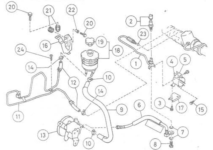
Figure 10.37. Power steering pipe system and reservoir: 1. Metal pipe of steering gear to gear housing,; 2. Pressure sensor; 3. Heat shield screw; 4. Clamp the front half; 5. Clamp the back half; 6. Pressure hose from pump to steering gear connection; 7. Washer; 8. Hydraulic connection bolt; 9. Pressure hose from tank to pump connection; 10. Hose clamp; 11. Metal return pipe from steering gear to reservoir; 12. Hose; 13. Pump; 14. Bracket; 15. Bolt; 16. Suspension; 17. Heat-resistant shield; 18. Assembling the tank; 19. Tank filler cap; 20. Bolt; 21. Rubber bushing; 22. Gasket; 23. O-ring seal; 24. Screw
1. The system includes a feed tank (installed between the right front suspension strut and the bulkhead) a large (pressure) hose from which it goes to the pump. A sealed line from the pump through a large diameter pressure hose goes to the connection before the steering gear (which contains a pressure sensor on early carburetor and Turbo models) and from there through a metal tube to the steering gear housing. Two long metal tubes run from the steering gear housing to connectors on the gear housing tube, on each side of the rack travel cylinder.
2. The return, from the steering gear housing to the reservoir, is a long metal tube, mounted on the inner wing group and connected at each end to a short flexible tube.
3. Before removing the tank, drain the liquid into a clean container. Disconnect the hoses. Installation is carried out in the reverse order. Fill the system with liquid, bleed air from the system.
4. To drain the fluid, disconnect the short flexible tube from the steering gear housing and drain the fluid into a suitable container. To speed up the process, connect a long plastic tube to the steering gear bushing and lower the other end into the container. Start the engine, at idle speed, rotate the steering wheel from lock to lock until all the fluid has drained. Stop the engine to avoid damaging the pump.
5. When installing the tank, check that the hose or tube is positioned correctly.
6. To check the pressure sensor, if present, disconnect the switch wires and connect a multimeter (in resistance measurement mode), to the sensor terminals. There should be no short circuit (that is, the resistance is infinite). Start the engine and set the idle speed, then turn the steering wheel completely from left to right. When the pressure rises above 1961-2942 kPa, at the maximum steering angle, the switch contacts should close. If not, the switch is faulty and must be replaced.
(The material is based on data from the portal NissanBook)