


Table of contents: Outer CV joint - removal and overhaul ↓ Outer CV joint - check ↓ Inner CV joint - removal and overhaul ↓ Inner CV joint - check ↓ Drive shaft - check ↓ Thrust bearing - removal and overhaul ↓ Thrust bearing - check ↓
1. Remove the drive shaft from the vehicle.
2. Note that all rubber boot clips, retaining rings and mounting clips must be replaced each time removal and installation procedures are performed.
3. Clean the shaft before disassembling, clamp it in a vice.
Outer CV joint - removal and overhaul
4. Remove the brackets of the protective cover, pull the cover from the connection to the middle of the cotton wool.
5. Remove the retaining bracket, remove the outer joint from the shaft assembly. Remove the boot, and finally the retaining bracket.
6. When installing, wrap the end of the wad with insulating tape to protect the rubber boots from damage. Install a new small bracket, put the boots on the drive shaft. Remove the tape, install a new mounting bracket in the groove at the end of the wad.
7. Install the outer CV joint onto the bat. If using the old CV joint, align the marks made before removal. Install the drive bat nut.
8. Fill the joint with the correct amount of grease of the specified type (supplied with repair kit), twist the connection and check that everything inside is filled with grease, squeeze the rest into the rubber boot
9. Pull the covers onto the outer joint, install the new large clamp and clamp it as shown in Figure 8.7, then bend the end and secure it under the clamp tabs as shown in Figure 8.8.
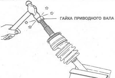
Figure 8.6. Installing the outer CV joint on the drive shaft
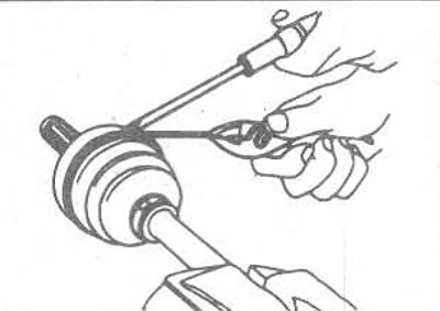
Figure 8.7. Compressing the drive shaft boot clamp
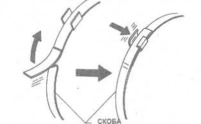
Figure 8.8. Secure the ends of the bracket with clamps
10. Install the boots so that their length is as shown in Figure 8.9, remove all air from the inside. Check that the smaller end is located in the groove of the drive shaft and check that the boots are not stretched or deformed. Install the smaller clamp on the boots, clamp it as shown in Figure 8.7, then bend the end and secure it under the clamp tongues as shown in Figure 8.8.
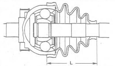
Figure 8.9. Installation length of the external connection cover: L = 96.0 - 98.0 mm
Outer CV joint - check
11. The external connection cannot be repaired and if it is worn or damaged, it must be replaced completely.
12. Clean the connection in solvent, dry it (compressed air).
13. Check each ball for corrosion or wear, inner and outer ball grooves.
14. Check the outer end of the connection. The threads and alignment along the entire length should be in good condition.
15. If the connection is worn or damaged, it must be replaced.
16. Note that on later models a shield is installed on the joint to protect the wheel bearing from dirt or water.
17. Inspect the rubber boot of the joint carefully for cracks, splits, or other wear or damage. Replace the boot if necessary.
Inner CV joint - removal and overhaul
18. Remove the cover clamps and pull the cover from the connection to the middle of the shaft.
19. Mark the position of the coupling body on the cotton wool, remove the coupling body from the spider. Mark the position of the spider on the cotton wool, remove the locking ring from the end of the cotton wool. Remove the spider and cover from the cotton wool (Figure 8.10).
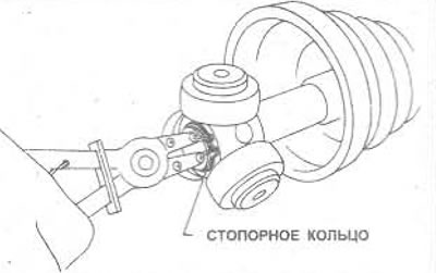
Figure 8.10. Remove the retaining ring
20. Installation is carried out in reverse order.
21. Apply grease around the spider rollers and into the coupling body. Place the coupling body onto the spider.
22. Pull the shrouds onto the coupling body, remove all air, install a new large clamp and clamp it as shown in Figure 8.7, then bend the end and secure it under the clamp tongues as shown in Figure 8.8.
23. Fit the boots so that their length is as shown in Figure 8.11. Check that the smaller end is positioned in the groove of the drive shaft and check that the boots are not stretched or deformed. Fit the smaller clamp onto the boots, clamp it as shown in Figure 8.7, then bend the end and secure it under the clamp tabs as shown in Figure 8.8.
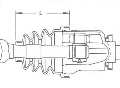
Figure 8.11. Installation length of the internal connection cover: L = 101.5- 103.5 mm
Inner CV joint - check
24. Clean the parts thoroughly using a suitable solvent to ensure that no traces of lubricant remain, then dry them with compressed air.
25. Check the condition of the CV joint assembly. If there is damage or wear, the spider must be replaced.
26. Check the condition of the CV joint housing, especially the spider rollers. Replace the housing if it is worn or damaged.
27. Check the rubber boots carefully. Replace them if there is any doubt about their condition.
Drive shaft - check
28. If both CV joints have been removed as described above, the condition of the drive shaft can be checked. Replace the drive shaft if necessary.
29. If the drive shaft needs to be replaced, note that they are only available as part of a complete assembly or as part of a drive shaft repair kit.
Thrust bearing - removal and overhaul
30. On 1.8 and 2.0 liter models, remove the bearing retaining ring with pliers.
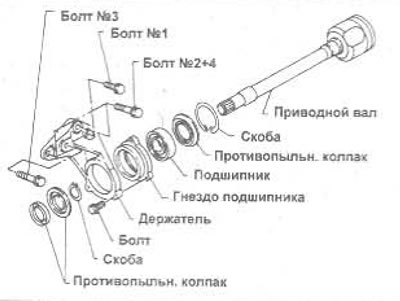
Figure 8.12. Assembling the holder bearing - 1.8 and 2.0 liter models only
31. Press the bearing housing and bearing out of the internal joint of the extended portion of the shaft as shown in Figure 8.13.
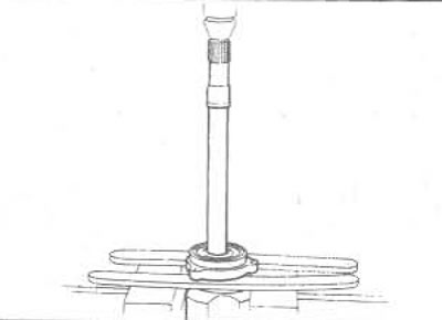
Figure 8.13. Installing the holder bearing on the inner CV joint shaft
For more information, see the website Nissanbook.ru
32. Turn the assembly over, remove the large retaining ring with pliers, then remove the dust shield.
33. When reassembling, apply lubricant to the housing, install the dust shield and a new large retaining ring (Figure 8.14). Make sure that the inner bearing race is fully supported. Press the extended part of the inner joint shaft into the bearing until the smaller snap ring fits into the groove.
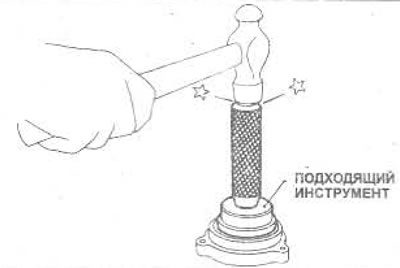
Figure 8.14. Driving the bearing holder into the housing - the tool should be applied to the outer ring of the bearing only
34. Install two dust shields on the bearing housing and the inner end of the drive shaft, respectively.
Thrust bearing - check
35. None of the components of the support bearing assembly are subject to repair (except for the bearing suspension and bolts). If there is wear or damage, they should be replaced. Nissan recommends that the bearing snap rings be replaced each time they are removed.
36. To check the bearing, clamp the inner ring and quickly rotate the outer ring, check whether there is any play between them. The bearing should rotate smoothly and smoothly, and there should be no play between the inner and outer rings.
37. Check all other bearing assembly components and replace if necessary.