


Table of contents: Disassembly ↓ Examination ↓
Disassembly
From the transmission side (main gear)
- Clamp the drive shaft in a vice. When securing the drive shaft in a vice, place copper or aluminum plates between it and the vice jaws.
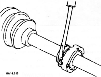
- Remove the cover clamps.
- Before separating the inner joint and drive shaft, apply alignment marks to the joint and shaft.
Front axle only
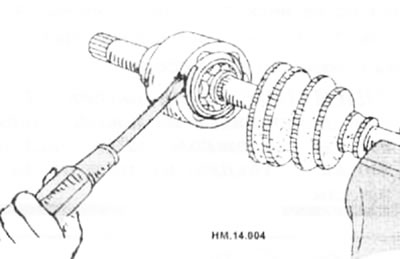
- Using a flat-head screwdriver, remove the retaining ring and pull out the inner joint housing.
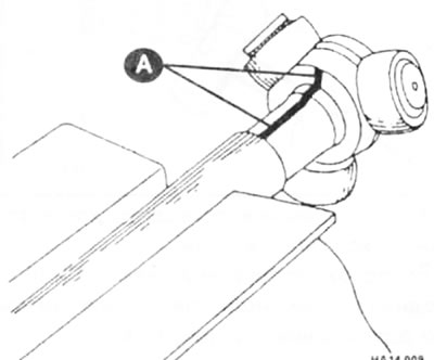
- Place alignment marks (A) on the tripod and on the drive shaft.
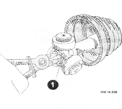
- Remove the retaining ring (1) and then pull the tripod off the shaft.
(Read more on the website: «www.NISSANBOOK.ru»)
- Remove the cover from the shaft.
- Use paper towels to remove old grease from the inner hinge parts.
Rear shaft only
- Remove the retaining ring and boot from the inner joint.
From the wheel side
- Clamp the drive shaft in a vice. When securing the drive shaft in a vice, place copper or aluminum plates between it and the vice jaws.
- Remove the cover clamps. After this, remove the cover from the outer hinge.
- Mark the position of the joint on the shaft and remove the joint from the shaft.
- Screw the drive shaft puller (arrow) 30 mm or more into the threaded portion of the outer joint. Pull the outer joint off the shaft.
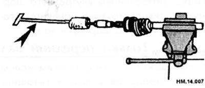
- If the outer joint cannot be removed after several unsuccessful attempts (5 or more), the entire drive shaft assembly must be replaced.
Caution: If the joint is to be replaced with a new one, knock it down with a hammer while clamping the shaft in a vice with soft metal jaws.
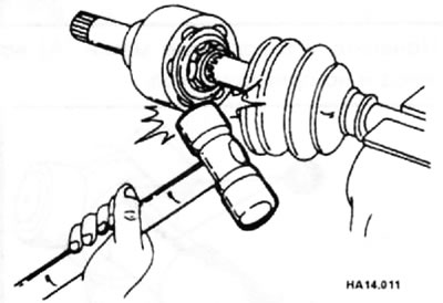
- Clean the drive shaft thoroughly and clamp the shaft again in a vice.
- Position the impact puller and drive shaft so that they are in line and pull the shaft out.
- Remove the cover from the shaft.
- Remove the retaining ring from the shaft.
- Rotate the separator and use paper towels to remove old grease from the outer joint.
Right front shaft (2-wheel drive models)
- Remove the boot from the inner hinge.
- Remove the retaining ring (1).
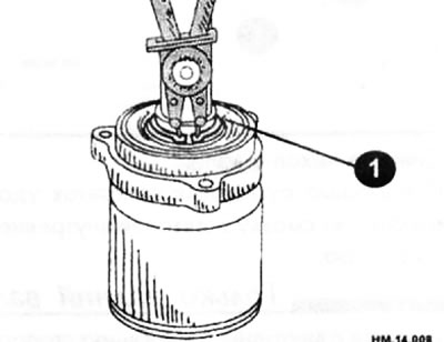
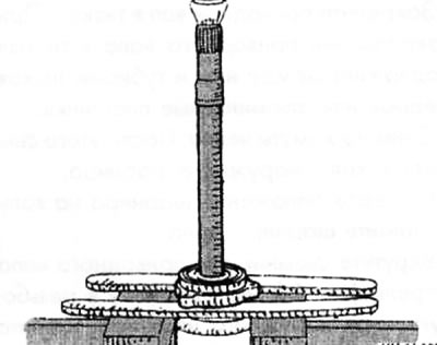
- Press the thrust bearing off the inner joint.
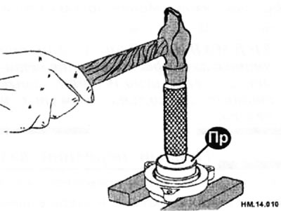
- Separate the support bearing from the bracket using the tool (Pr).
- If there is a damper, remove it by loosening the weight clamp.
Caution: Mark the position of the weight relative to the shaft.
- When installing the damper, make sure that the mounting clamp fits into the shaft groove. If there is no groove, align the weight according to the marks applied earlier.
Examination
- Check the drive shaft.
- If the shaft has runout, cracks or other damage, replace it.
- Check the outer joint.
- Make sure that there is no difficulty or unusual movement in the axial direction when rotating the joint.
- Make sure that no foreign objects have entered the outer hinge.
- Check the outer hinge for scratches, cracks or breaks.
Caution: If the outer joint has any unusual features, the entire outer joint must be replaced.
- Check the housing from the inner hinge side.
- Make sure there are no scratches, cracks or breaks on the surface on which the balls move, that there is no damage to the drive shaft threads, and that there are no deformations on the parts used to secure the covers.
- Check the working surface of the separator and the steel balls for scratches, cracks or fractures.
- Inspect the surface of the inner race that contacts the balls for scratches, cracks or chips.
- Make sure there is no damage to the toothed portion of the sleeve.
Note: If any damage is found on the parts, they must be replaced with new ones (separator, balls and inner race).
- Check that the support bearing rollers rotate freely, do not make noise, and are free of cracks, dents, or signs of wear.
- Check the damper for cracks or wear. When installing the damper, its clamps must be replaced.
From the transmission side (main gear)
- Install a new boot and a new, smaller clamp onto the shaft. To prevent damage to the boot during installation, wrap the drive shaft splines with protective adhesive tape.
- Remove the protective tape that covers the drive shaft splines.
- Install the tripod securely, ensuring that the alignment marks made during removal are aligned exactly with each other.
- Install a new snap ring.
- Fill the drive shaft joint with fresh grease in the amount of 230-250 g for the front shaft and 85-95 g for the rear shaft.
- Install a new snap ring onto the inner joint.
- After installation, pull the drive shaft to check the alignment of the outer joint and the snap ring.
- Place the cover securely into the grooves indicated by the arrows in the figure.
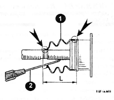
- If on the mounting surfaces (in the grooves) there is grease on the boot on the drive shaft and on the hinge housing, the boot may shift. Grease must be removed from the surfaces.
- Make sure that the installation length of the boot (1) is 123 mm for the front shaft and 67.7 mm for the rear shaft. Insert a flat-head screwdriver or similar tool (2) under the cover from its smaller side. To prevent deformation of the cover (1), it is necessary to remove air from it.
Caution: If the installation length of the cover is less than the value specified above, the cover may be damaged. Be careful not to touch the inside of the case with the tip of the screwdriver.
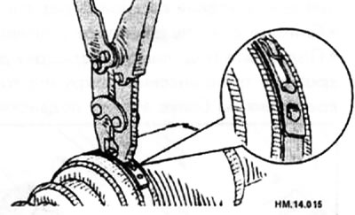
- Securely fasten both ends of the cover with clamps, using special pliers.
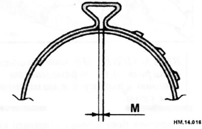
- The cover clamp must be secured in such a way that the dimension "M" shown in the figure is equal to 1.0-4.0 mm.
- After installing the hinge housing and drive shaft, rotate the boot and check that it is in the correct position. If the cover is not positioned correctly, re-secure the cover using new clamps.
Front wheel drive only
- When installing the damper, use new clamps.
- Install the damper on the outer hinge side, which must be held stationary, maintaining dimensions "A" and "B" as shown in the figure below.
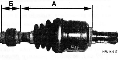
A = 207-213 mm; B = 70 mm.
From the wheel side
- Fill the inner cavity of the outer joint (1) with NISSAN brand grease or similar until old grease begins to emerge from the groove for the movement of the balls. After filling with grease, it is necessary to remove the old grease that has come out using a napkin.
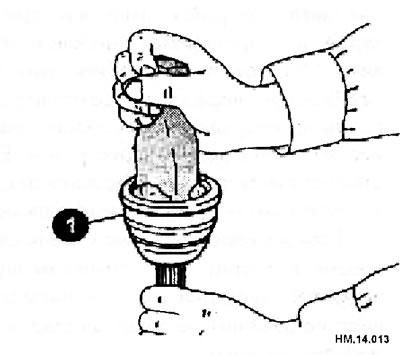
- Wrap the splined portion of the drive shaft with protective tape. Install a new boot and a new small boot clamp onto the drive shaft. Be careful not to damage the case.
- Remove the protective tape that covers the drive shaft splines.
- Install a new retaining ring onto the shaft. The retaining ring must fit securely into the groove on the shaft. Screw the nut onto the outer hinge. Use a wooden hammer to press the hinge in.
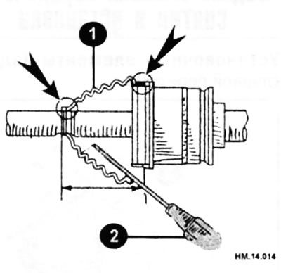
- Fill the outer joint boot (1) with fresh NISSAN grease or equivalent in the amount of 145-165 g for the front shaft and 75-85 g for the rear shaft through the large end of the boot by inserting a flat-head screwdriver (2).
- Make sure that the installation length of the boot (1) is 96.5 mm for the front shaft and 79.6 mm for the rear shaft.
- Install a new large clamp.
Caution: If the installation length of the cover is less than the value specified above, the cover may be damaged. Be careful not to touch the inside of the case with the tip of the screwdriver.
- Secure both ends of the cover with new clamps as shown in the picture.
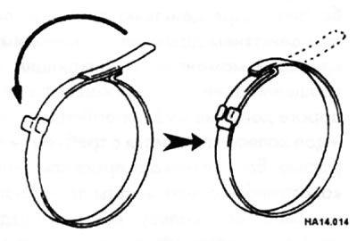
- After installing the hinge housing and drive shaft, rotate the boot and check that it is in the correct position. If the cover is not positioned correctly, re-secure the cover using new clamps.